Updated October 27, 2026
Pool Bond Beam Width, Coping Setback and Track Fastener Edge Distance
Pool cover track fastener edge distance is measured from the fastener center to the actual edge of its anchoring material. For a vertical fastener into a concrete bond beam, calculate that position from the beam width, coping projection and track hole pattern, then check both concrete edges.
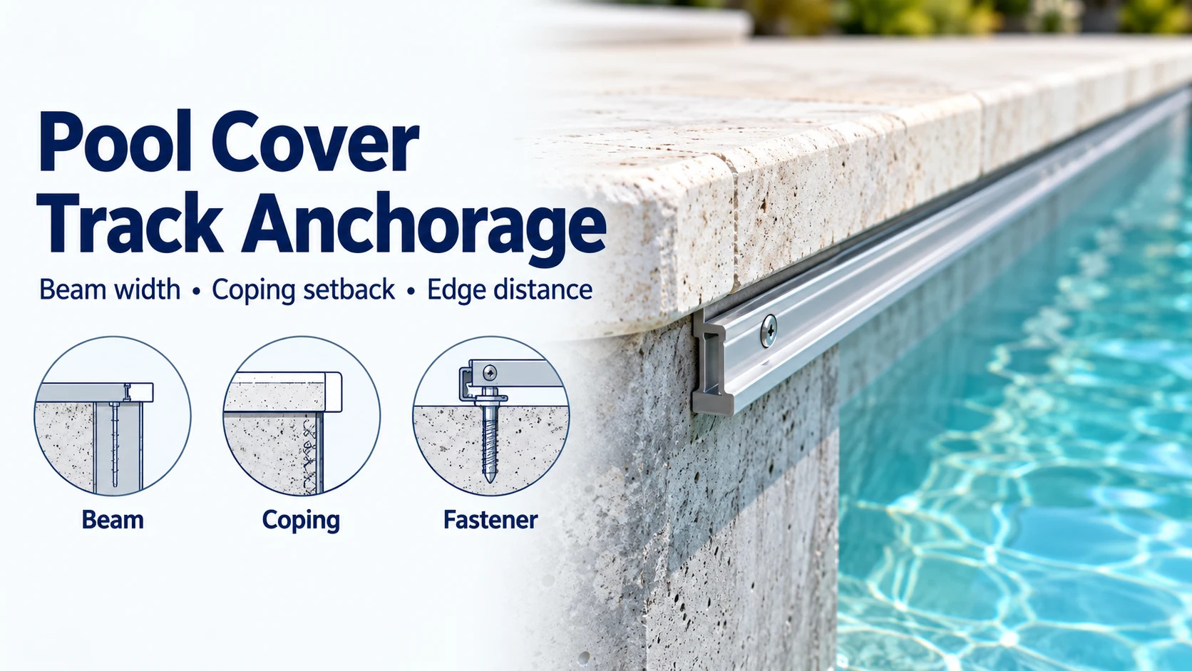
For wall-top concrete anchorage, the hole position is xᵢ = q + aᵢ − C; the available edge distances are xᵢ and B − xᵢ. Both must meet the selected assembly's requirements while the track stays within its permitted travel position. Start by identifying the attachment: an upward screw into coping and a downward fastener into a concrete beam use different substrates and checks. The workflow below gives a common measurement datum, a placement interval for every hole row, and a parameter checklist for coordinating the pool edge.
| Quick check | Record before calculating |
|---|---|
| Fastening arrangement | Screw-on coping, wall-top encapsulation, or the selected system's other approved detail |
| Structural width | Actual concrete width B at the anchorage, measured between structural edges |
| Coping projection | C from the same concrete edge to the coping nose |
| Track location | q from coping nose to profile reference; aᵢ from that reference to hole center |
| Acceptance | Both edge distances, spacing, embedment, member thickness and moving-part clearance |
Which material carries the track fastener?
Identify the load path before choosing an edge-distance rule. In a screw-on undertrack detail, the fastener can anchor upward into the coping. In a wall-top encapsulated detail, a sleeve carries the guide and attaches to the pool wall. The pool cover track systems guide explains these interfaces; use the undertrack guide to identify the hardware on the selected drawing.
Coverstar's Gunite Pools Photo Guide, printed pages 2–3, separates these two arrangements. Its screw-on detail relies on three connections: anchor to coping, the coping's own strength, and coping to wall. Aquamatic's Hydramatic Undertrack & Top Recess Installation Manual, printed page 6, likewise describes plastic anchors and stainless screws installed into the coping underside. A generic metal expansion-anchor table cannot qualify those kits.
Coverstar's Encapsulation Instructions L9645, page 2, calls for a mortar leveling bed providing at least 3 in of flat, straight, level mounting surface. That dimension describes the mounting seat for this assembly. Structural beam width still needs its own measurement. A leveling bed can be part of the specified construction; a concrete-rated anchor must develop its resistance in the concrete required by its evaluation report.
Where do beam width and coping setback start?
Use the pool-side structural concrete edge as the common horizontal zero. Mark the concrete top separately as the vertical datum. Tile, render, mortar and the coping nose can hide the structural edge, so transfer the survey or exposed-concrete measurement onto the section before comparing dimensions.
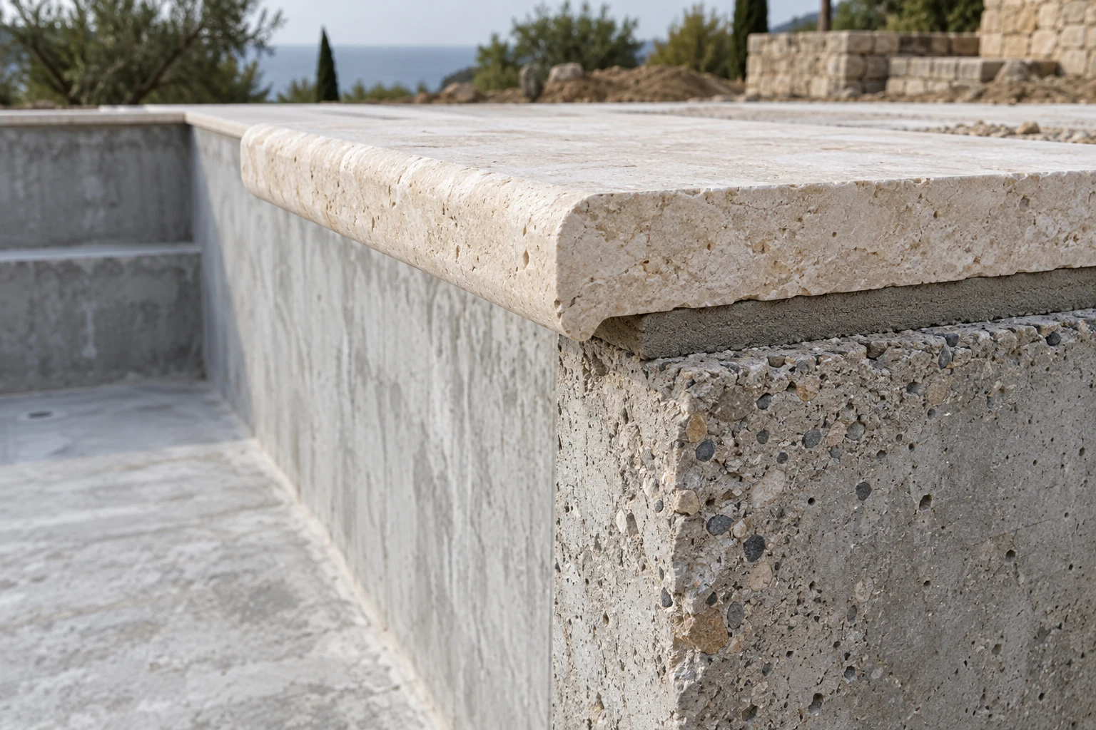
Use one length unit throughout the calculation. In the following wall-top section, positive x points toward the deck; the pool-side concrete edge is x = 0 and the opposite edge is x = B.
| Symbol | Meaning and measurement |
|---|---|
| B | Structural concrete width at the anchor section; exclude projecting coping and unverified topping |
| C | Coping projection poolward from the structural zero; the nose is at x = −C |
| q | Signed deckward distance from coping nose to the chosen pool-side reference edge of the track profile |
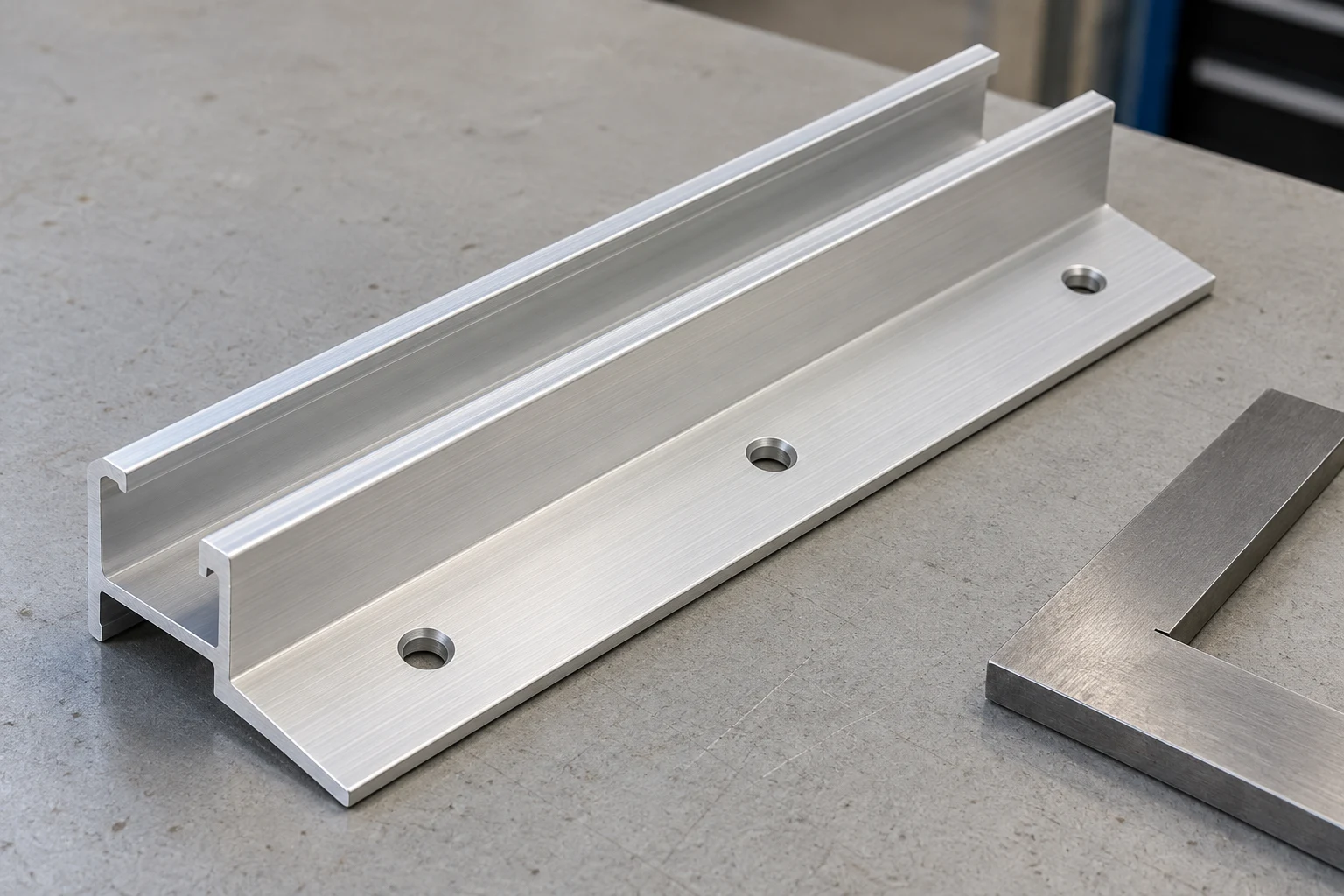
| aᵢ | Deckward offset from that profile reference to fastener center i, taken from the actual hole pattern |
| W | Profile base width; record it for fit, but obtain aᵢ from the drawing or measurement |
| c_req,in and c_req,out | Required pool-side and deck-side edge distances for the selected anchor assembly and design load |
For a wall-top fastening line, an overhanging coping nose establishes a finish reference; it does not move the concrete edge. A measurement taken from finished tile must be converted to the structural datum. Record mortar thickness on the vertical section so it can also be accounted for when checking fastener length and embedment.
How do you calculate each fastener's edge distance?
Locate each hole center, then subtract its position from the beam width to find the opposite edge distance. These equations describe vertical fasteners into a straight concrete wall top. Upward coping fasteners require the coping detail's own substrate, support and edge checks.
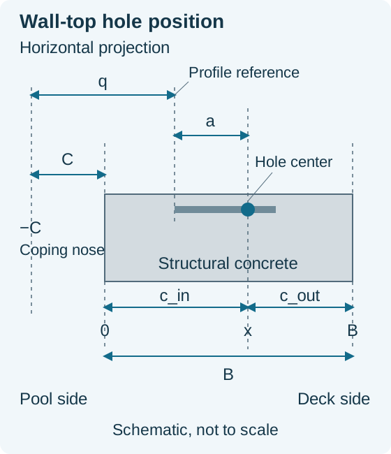
The nose starts at −C. Moving deckward by q reaches the profile reference; moving another aᵢ reaches the hole center:
xᵢ = q + aᵢ − C
c_in,i = xᵢ
c_out,i = B − xᵢ
A hole has a geometrically acceptable transverse location only when both required distances fit:
c_req,in ≤ q + aᵢ − C ≤ B − c_req,out
Rearranging gives the permitted track-reference position for each hole row:
C + c_req,in − aᵢ ≤ q ≤ C + B − c_req,out − aᵢ
Apply that interval to every row. If required edge distances differ by anchor or row, use the corresponding requirements in each interval. Next intersect those intervals with the manufacturer's permissible track position and the project's construction-tolerance allowance. The largest lower bound must be no greater than the smallest upper bound.
If the intervals have no common overlap, revise the section before drilling. Moving the track may resolve one edge distance while violating the other or reducing slider clearance. A beam satisfying B ≥ c_req,in + c_req,out meets only a necessary width condition; multiple hole rows, wall ends, corners, anchor spacing and load resistance still need checking.
Which anchor-table dimensions belong together?
Read edge distance, spacing, thickness and embedment from the same applicable anchor configuration. The required design edge distance must satisfy the installation minimum and the resistance checks for the actual load and concrete condition. A minimum edge-distance cell alone is not a capacity approval.
A concrete-anchor report shows why these terms must stay separate. ICC-ES ESR-3037, reissued August 2026, Table 1B, lists the following for the ¼-in stainless-steel Simpson Strong-Tie Strong-Bolt 2. The report evaluates this diameter for uncracked concrete. This is a table-reading example for that anchor; pool-cover fastening selection follows the approved cover assembly.
| Table 1B entry | Value for this column | What to distinguish |
|---|---|---|
| Nominal embedment | 1¾ in | Physical installation embedment defined by the report |
| Effective embedment | 1½ in | Depth used in the resistance model |
| Minimum hole depth | 1⅞ in | Drilled depth required for installation |
| Minimum edge distance | 1¾ in | Installation geometry requirement |
| Critical edge distance | 2½ in | Separate edge-effect parameter used with the report's design provisions |
| Minimum anchor spacing | 2¼ in | Center-to-center spacing between anchors |
| Minimum concrete thickness | 3¼ in | Thickness of the concrete member receiving the anchor |
| Installation torque | 4 ft-lbf | Specified setting torque for this configuration |
ESR-3037 sections 4.1.10–4.1.11 and 4.3 connect these entries to design and installation conditions. Some larger-diameter columns use alternative spacing/edge-distance combinations: keep the chosen combination intact. Substituting a screw or anchor of similar diameter does not transfer the report's values to that product.
For the job sheet, record the exact anchor designation and material, substrate condition, applicable spacing/edge-distance combination, thickness, installation method and required resistance. Resolve those before inserting c_req,in and c_req,out into the geometry.
How does coping cantilever change track clearance?
A larger projection moves the hole closer to the pool-side concrete edge only if the track stays at the same position relative to the coping nose. In the equation, increasing C while holding q and aᵢ fixed reduces xᵢ. If the track position changes independently, recalculate the complete section.
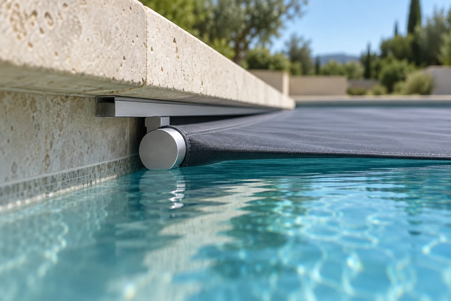
The coping integration guide explains how the finish and track interface meet. Check the chosen guide, slider, bar-end hardware and leading-edge bar throughout their travel, including transitions at the cover box. Aquamatic's Hydramatic manual, preliminary checks 6–7 on printed page 2 and track installation on printed page 6, treats the coping underside and the passage below it as distinct installation constraints.
A track moved inward to gain fastening access can alter the space available to the bar and its end hardware. A track moved deckward can run out of the structural edge-distance allowance on the other side. Keep the approved track position, parallel guide layout and clearance envelope on the same marked-up drawing as the anchor centers.
What should stop drilling or trigger a revised detail?
Stop when the substrate or geometry differs from the detail used to select the fastener. Drilling damage at a coping edge, concrete breakout under load and loss of coping bond are different problems. The fastener, substrate and load path determine the remedy.
| Finding | Consequence to assess | Next action |
|---|---|---|
| Hole enters only mortar or topping, although the selected anchor requires concrete | Effective anchorage differs from the approved concrete condition | Locate the structural concrete and revise the fastening detail and length |
| Required hole-row intervals do not overlap | At least one edge or travel requirement conflicts | Revise the track/beam/coping section with the installer and designer |
| Chipping or cracking appears at the hole or coping edge | Drilling breakout or substrate damage | Stop installation and have the damaged material and connection assessed |
| Coping rocks or its bond is unsound in a screw-on arrangement | The coping-to-wall part of the load path is compromised | Resolve the support and bond before loading the guide |
| Bar-end or slider hardware rubs after repositioning | The selected track position conflicts with the travel envelope | Reconcile the track position and clearance drawing before operation |
The Hydramatic manual warns against drilling through the coping top or breaking its edge during its screw-on installation. ESR-3037's concrete-anchor provisions address separate structural checks. Avoid treating visible spalling as permission to move a hole slightly, change anchor type or cut reinforcement without a revised approved detail.
Questions that affect the final detail
Can reinforcement make a too-small edge distance acceptable?
Reinforcement affects an anchorage design only through the applicable design provisions and its verified layout. Have the designer assess the selected anchor, loads and reinforcement together. Finding steel near a hole is a reason to resolve the drilling location, not to assume the edge-distance requirement is satisfied.
Can total screw length be used as effective embedment?
Use the embedment definition in the selected fastening document. Screw length can include the profile, bedding and other layers above the structural base material. Record nominal embedment, effective embedment and required hole depth separately; the ESR-3037 example shows that these can have different values.
Does the two-edge calculation cover wall ends and corners?
It checks the two transverse edges of the defined straight section. Add longitudinal end distances, nearby returns, neighboring anchors and the full anchor-group assessment. A satisfactory mid-wall section can still have a different controlling edge at the end of a track.
Parameter checklist for the installer and designer
Hand over one coordinated section with the anchor and moving-part requirements attached. Include:
- The cover model, track/encapsulation drawing, fastener kit and drawing revision.
- Concrete beam clear width B, both structural edges and the top-of-concrete datum.
- Coping projection C, the datum used to measure it, and coping material, thickness and support condition.
- Mortar or topping thickness and the substrate in which anchorage is developed.
- Profile base width W, reference position q and every hole-center offset aᵢ.
- Fastener type, diameter, material, nominal/effective embedment and required drill depth.
- Required edge distances, permitted spacing combination, concrete thickness and load checks.
- Wall ends, corners, reinforcement location, construction tolerances and the cover's complete travel envelope.
- The accepted common position interval and approval of any changes to the fastening or coping detail.
Use this sheet alongside the undertrack attachment detail and pool cover track systems overview when coordinating the pool builder and cover installer.
Technical references
Updated October 27, 2026.
- Aquamatic, Hydramatic Undertrack & Top Recess Installation Manual: printed pages 2 and 6, preliminary checks and screw-on track installation.
- Coverstar, Encapsulation Instructions L9645: page 2, leveling bed and wall fastening sequence.
- Latham/Coverstar, Gunite Pools Photo Guide L0021.23_R1: printed pages 2–3, screw-on and encapsulated load paths.
- ICC-ES, ESR-3037, reissued August 2026: Table 1B and sections 4.1.10–4.1.11 and 4.3, stainless-steel anchor installation dimensions and associated conditions.