Updated October 2026
Pool Safety Cover Installation and Deck Anchoring
A moving anchor or misplaced strap can compromise a manual safety cover even when the fabric is intact. Pool safety cover installation and deck anchoring require the supplied anchor plan, hardware suited to the actual concrete or paver deck, and spring settings for the cover material. Identify the pool safety cover system before laying out any holes.
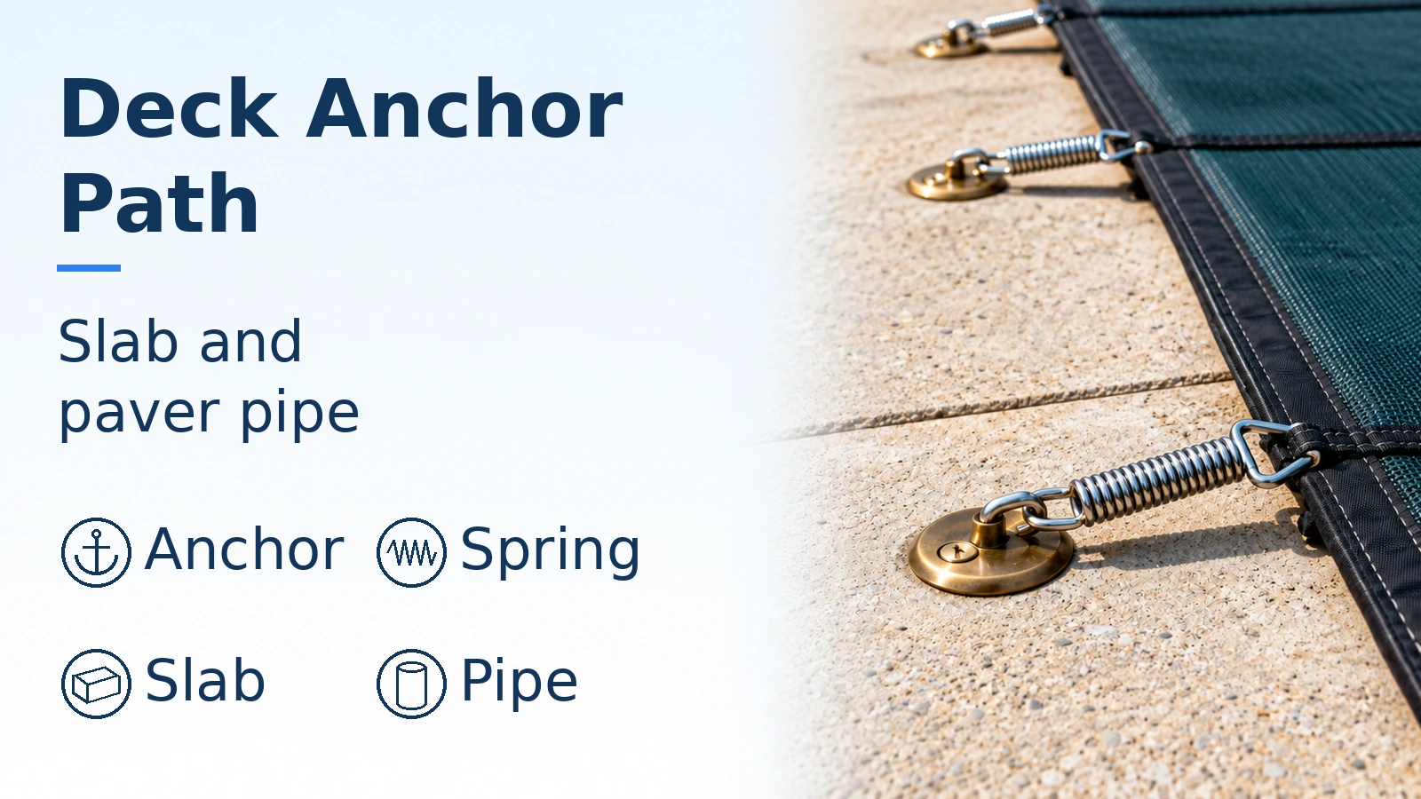
What must be known before the first hole?
Install a manual safety cover from its own anchor plan and installation instructions, with the deck construction confirmed before drilling. The plan establishes where straps pull; the substrate establishes how those forces reach a stable support. Concrete deck anchors and paver anchor-in-pipe assemblies have different details. Existing holes are reusable only when the replacement cover’s approved layout and hardware match them. Spring tension cannot correct the wrong geometry or an unstable base.
This guide concerns manually fitted mesh and solid covers with straps and springs. Automatic-track installation involves guides, a moving leading edge, and a drive; it is a different system and these anchor dimensions do not apply to it.
- Confirm the exact cover, material, anchor plan, installation revision and supplied spring/hardware set.
- Identify solid concrete, pavers over sand, pavers over a slab, or another deck construction; do not infer the base from the surface finish.
- Locate buried services, deck joints, drains, repairs, raised walls and steps before choosing drill points. A conflict needs an approved revised detail.
- Identify pool-water support, surface drainage, coping protection and an inspection procedure for the completed installation.
Concrete and pavers need separate anchoring paths
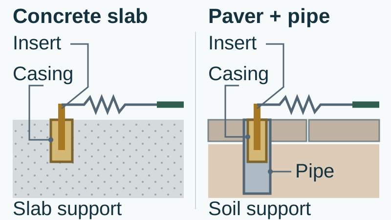
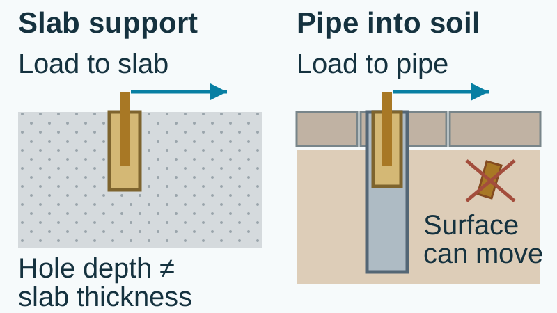
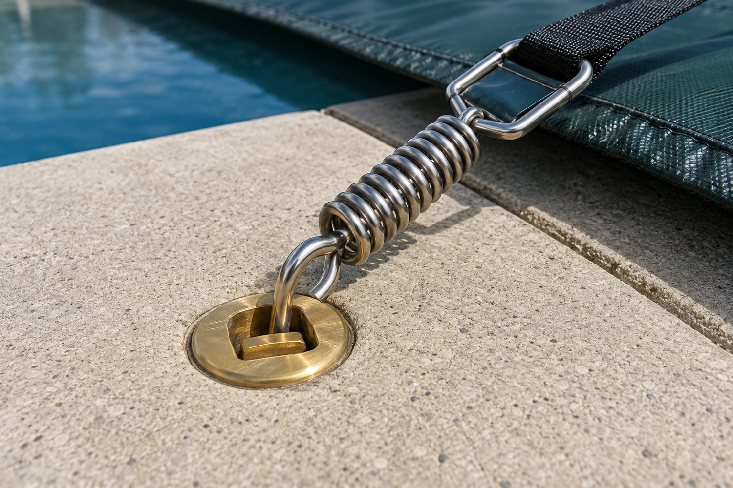
Concrete uses the brass casing detail specified for that slab and hardware. In the retrieved LOOP-LOC installation guide, page 2, its concrete detail calls for a ¾-inch-diameter hole drilled 2¼ inches deep, followed by seating the casing and threading the insert. These dimensions were checked October 19, 2026 and apply to that anchoring detail. Hole depth is not a statement of required slab thickness, allowable edge distance, or a universal anchor embedment.
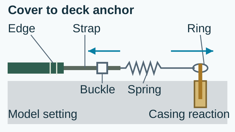
The same page requires anchor-in-pipe for brick, stone or pavers laid on sand or on a cement slab. The brass casing is secured in the pipe, which passes through the finished surface into the ground. Figure 5 identifies a minimum 15 inches into soil. This is the cited LOOP-LOC assembly, not permission to use a short concrete anchor in a loose paver. Slab-under-paver conditions still need the pipe route described by this manufacturer.
Rules of thumb: for that anchor-in-pipe detail, if the installed pipe reaches less than 15 inches into soil, Figure 5’s support condition is unmet. A loose or rocking paver also requires investigation before tensioning. Do not treat visible pipe length, deck thickness, or an unsupported cavity as soil engagement. Another manufacturer may prescribe a different tested anchoring assembly.
| Deck or condition | Specified path | Dominant Failure Mode & Prevention |
|---|---|---|
| Sound concrete, suitable approved location | Manufacturer’s concrete casing and insert detail | Casing loosens or deck cracks → confirm substrate and location, then use the specified hole and seating method |
| Brick, stone or pavers over sand or slab | Cited LOOP-LOC anchor-in-pipe route, page 2 | Anchor pulls against a moving surface unit → carry the casing in the specified pipe assembly into its support |
| Cracked slab, narrow edge, unsupported deck or utility conflict | Resolve the substrate or obtain a revised detail before drilling | A correctly sized hole in an unsuitable location still fails → inspect the underlying structure and document the approved repair/layout |
Lay out from the cover edge, then check the whole perimeter
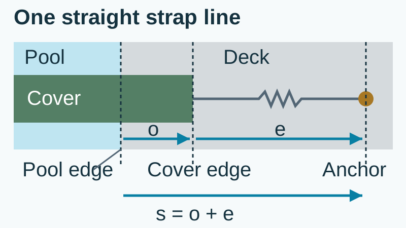
Anchor setback must be measured from the reference line the manual names. The LOOP-LOC guide, page 1, first aligns cutouts and equalizes cover overlap, then marks its standard anchor positions 20 inches from the cover edge; it separately lists 22 inches for commercial covers. These October 19, 2026 fetched dimensions are not measurements from the waterline, not the overlap itself, and not the distance between neighboring anchors.
Formula: pool-edge-to-anchor distance s = cover overlap o + cover-edge-to-anchor distance e, measured along the same straight strap line on a flat deck. Illustrative standard-detail inputs: a hypothetical overlap o = 12 inches and the cited e = 20 inches give s = 12 + 20 = 32 inches. The 12-inch input is an illustration, not a required overlap. Oblique straps, steps, and raised walls need their supplied plan rather than this one-dimensional example.
Use the plan’s initial opposing straps to hold the aligned cover, then complete the remaining anchors in the manufacturer’s sequence. On the cited rectangular detail, corners are installed last and perimeter anchors are aligned from the established positions. Do not turn the 20-inch setback into a universal spacing grid. Check that no service hatch or deck fitting is being used as a structural anchorage.
Spring adjustment follows the material, not the neighboring pool
Use the setting for the supplied spring and cover. The LOOP-LOC guide, page 3, gives approximately 85–90% initial compression for its new in-ground mesh covers, with rechecking after 2–3 weeks, and approximately 60% for its in-ground ULTRA-LOC solid covers. The mesh care sheet, page 1, calls for maintaining approximately 75% in-ground mesh compression. All were checked October 19, 2026; these are manufacturer-described compression settings, not strap stretch percentages or universal spring-force measurements.
Thread straps and operate the installation rod as the supplied diagrams show. Balance the specified adjustment around the perimeter while keeping the cover correctly aligned and lying flat on the deck. Increasing tension against a loose anchor, damaged spring, or unsupported deck is a stop condition. A repair is needed before final adjustment.
Check mesh safety-cover requirements or solid-cover drainage options for the material being fitted. A panel-drained solid cover needs a drainage check as well as a spring setting; a pump-drained cover needs its water-removal system in place.
Handover checks must include water, gaps and future visits
The completed installation needs a perimeter inspection and an owner maintenance plan. Verify every anchor and spring against the drawing, inspect cover-edge contact at coping and obstructions, and confirm drainage without entering the cover. Raised walls and steps require the cover’s specified barrier treatment; a neatly tensioned sheet does not prove that an opening at an obstruction is closed.
Water beneath the cover remains part of the support system. The cited installation guide, page 1, specifies water 15–18 inches below the top of the pool for its in-ground mesh covers and 12–16 inches for solid. Record the actual datum and range for the installed model. Do not use anchor tension to make up for winter water loss.
Use the ASTM F1346 evidence checklist for the exact installed system. ASTM’s public scope links intended protection to correct installation and use; material alone is not an installation approval. Keep people off the cover and make provision for security whenever it is removed.
- Record the cover identification, dated anchor plan, hardware, substrate detail and any approved deviations.
- Inspect all anchor casings for movement, inserts for correct engagement, and springs and straps for damage or misalignment.
- Check raised-wall treatments and coping contact; add the manufacturer’s specified protection at abrasive surfaces.
- Confirm drainage and pool water height; document who returns after initial settling, storms, deck movement or a water-level change.
- Include winter inspections, drain/pump service, anchor cleaning and eventual deck repair in the ownership budget. A cheaper surface-only installation can create repeat repair and cover replacement work.
Method and sources
Updated October 2026. The numerical installation examples use LOOP-LOC’s manufacturer-authored Inground Cover Installation Guide, undated retrieved copy hosted by poolcovercenter.com, fetched October 19, 2026: page 1 for layout, setback and water heights; page 2 and Figure 5 for concrete versus paver details; page 3 for spring installation and adjustment. Its mesh care document, pages 1–2, was fetched on the same date. The older guide is a scoped worked reference; the instructions and anchor plan supplied with the exact current cover govern the job.
ASTM’s F1346-23 public title and scope were fetched October 19, 2026. Only public scope is used; the full test clauses were not available in that public record. No general anchor spacing, slab thickness, edge clearance, torque, spring force or snow rating is inferred. The dimensional example explicitly labels its illustrative overlap input.
Parent hub: Pool Safety Covers