Updated October 2026
Automatic Pool Cover Limit Switch and Rotary Encoder Troubleshooting
For a pool cover limit switch or encoder stop problem, identify the controller and sensor before choosing an adjustment procedure. Record the failing direction, the displayed message and the stopping position. Use the automatic pool cover parts guide to organize the equipment record, then select the matching checks below.
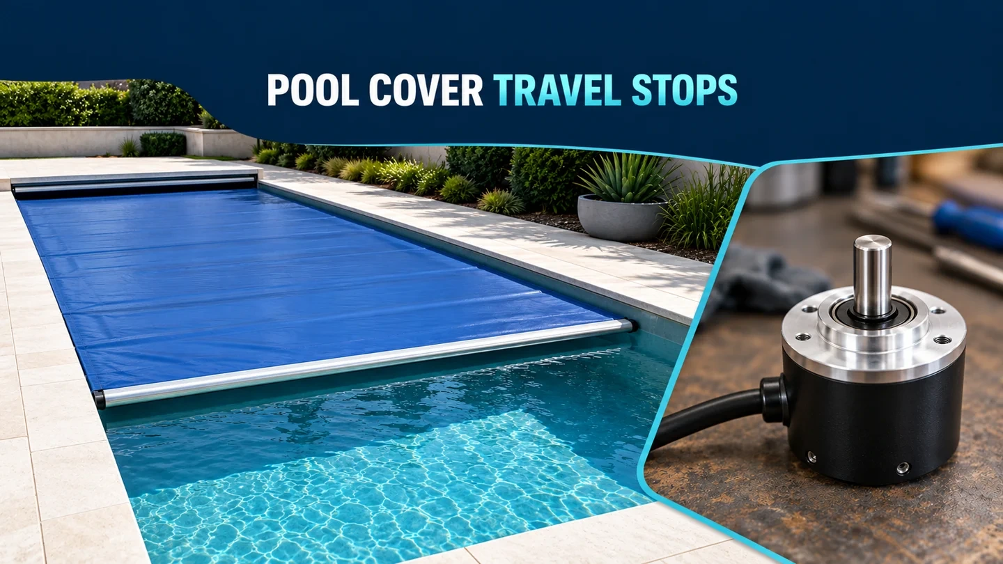
Start with the sensor’s job: motor shutoff vs water-feature interlock
Identify the motor-stop function and the water-feature function separately in your service notes before changing any limit setting.
In the Cover-Pools rotary-switch and AquaLink interface installation, the rotary switch communicates open, partially closed, and closed cover states.
In that Cover-Pools configuration, a high voltage switch operates the pool cover manually.
For the Latham feature-control configuration, with MOTOR INT. enabled, the motor shuts down when the sensor for that direction is triggered.
With motor interlock disabled, the motor ignores the sensors while the feature relay still responds.
Record the active interlock setting in the equipment file before selecting a motor-stop adjustment procedure.
Compare cover-mounted magnets with roll-up-tube rotation counting
For the Latham 1601 controller, Option 1 uses cover-mounted magnets and a sensor near the guide feed to determine cover position.
Option 2 uses a roll-up-tube magnet and a frame-mounted sensor to count cover rotations.
Option 1 provides better accuracy; Option 2 is easier to configure.
Use these option names when documenting this Latham controller configuration, and verify the installed sensor arrangement before starting adjustments.
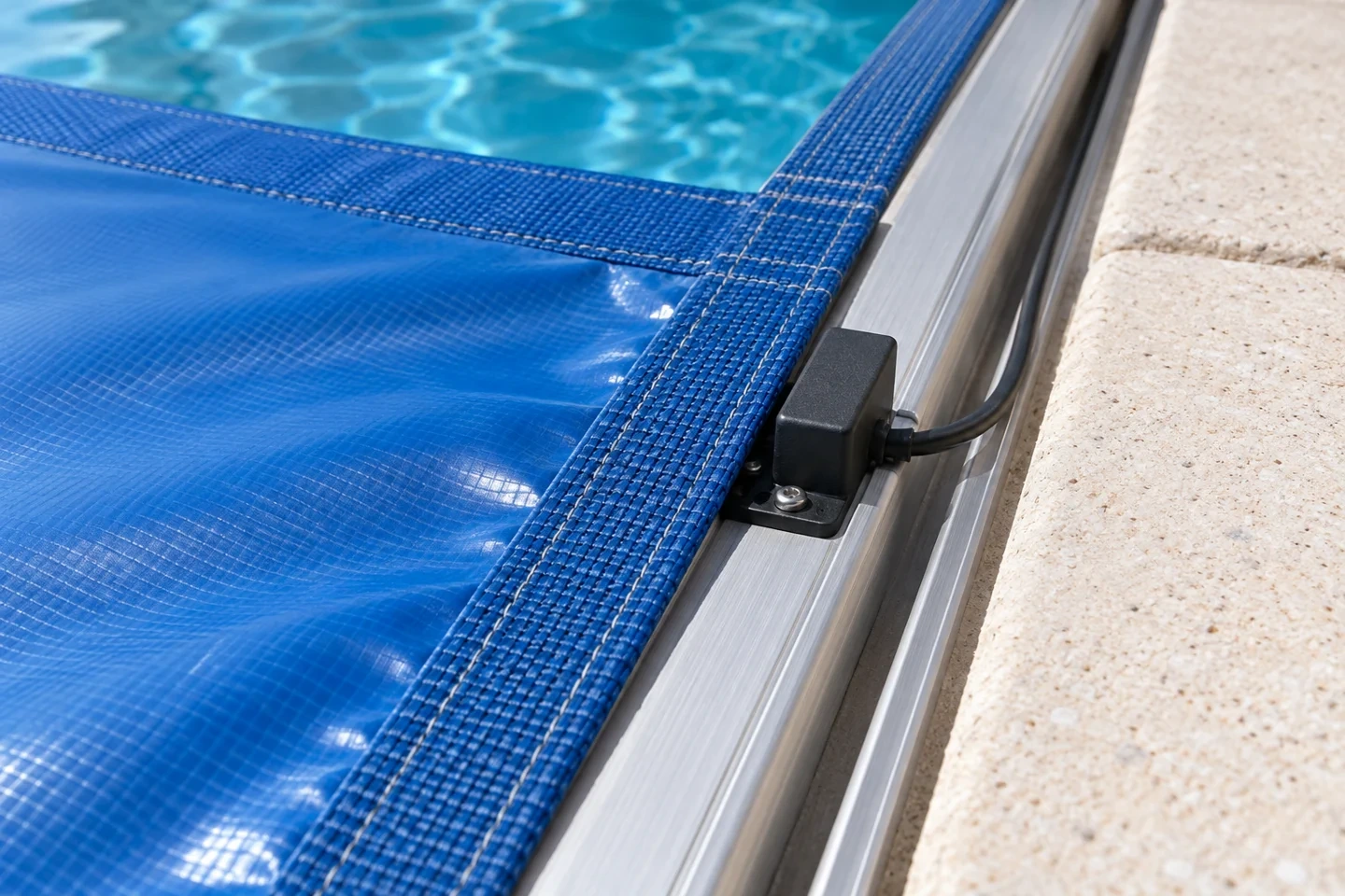
Webbing magnets, Hall-effect polarity and reed-switch direction
In the Latham 3 Wire Motor Limit Control installation instructions, the 3 Wire Motor Limit Control was not designed to work with 5 wire motors.
In this Latham installation procedure, shut off the breaker before working on electrical equipment.
In this Latham installation, the limit control enclosure should be mounted as high as possible in the cover box.
In this Latham installation, builder-supplied wire colors may differ; match the wires at each end.
The Latham installation check triggers the sensor with a magnet while the cover is running.
In the Latham installation instructions, the Hall Effect Sensor is polarity sensitive; if the cover does not stop, flip the magnet and try again.
In the Latham installation instructions, the reed-switch sensor needs to be matched to the run direction by switching the S1 and S2 leads if it does not stop.
In the Latham sensor installation, the magnet is inserted into the cover’s webbing through the slit.
In the Latham sensor installation, the close magnet is positioned so it just starts to cover the sensor.
In the Latham sensor installation, pushing the magnet farther into the webbing is easier than pulling it back.
In the Latham sensor installation, when opening the cover to the desired open-stop position, there is not yet an open stop.
In the Latham sensor installation, the open magnet is positioned so it just sits over the sensor.
After Latham sensor installation, check that the cover stops correctly in both directions and adjust as needed.
For a magnetic reed switch or leading-edge travel complaint, photograph the webbing slit and sensor bracket before moving either magnet.
End-travel pass distance, momentum travel and adapter status lights
For the Latham controller Sensor and Magnet Placement Option A configuration:
The cover-mounted magnet should pass within 1/2 inch of the sensor.
Momentum allows about 1 to 2 inches of cover travel after magnetic detection.
The trigger mechanism is ignored for the first few seconds to prevent a false trigger from a magnet in the opposing direction.
For Automatic Pool Covers AutoGuard magnet placement and Sensor Motor Adapter status indications:
In the Automatic Pool Covers AutoGuard magnet installation note, the magnets travel approximately 1” past the sensor before the cover stops.
On the Automatic Pool Covers Sensor Motor Adapter status label, the yellow status light means the motor torque limit has been reached.
On that Sensor Motor Adapter status label, the red status light means the cover has traveled as far as possible in the moving direction.
In your automatic pool cover end-travel stop adjustment notes, distinguish magnetic detection distance from momentum travel and record the status light shown.
Non-motor-end rotary limit switches and roll-up positioning variation
The Latham Mechanical Rotary Limit Switch is designed to provide a simple means to override water features to prevent water flowing onto the cover when the cover is deployed.
The switch detects cover rotation to determine whether the leading edge is behind or in front of home.
Different cover roll-up patterns can cause exact positioning to vary up to 1 foot.
For the Latham Mechanical Rotary Limit Switch, maximum switching current is 3 AMPS.
For the Latham Micro-Rotary Limit Switch, maximum switching current is 2 AMPS.
On the Latham Micro-Rotary Limit Switch, exact cover positioning can vary up to 1 foot because of different roll-up patterns.
For the Latham Micro-Rotary Limit Switch, a single flash, no flash, or failure to operate during home setting may require internal battery replacement.
For the Latham Rotary Encoder Setup and Testing procedure when the feature fails to turn on at home:
Check that the magnet remains in the sensor disk.
Check whether the sensor disk bumps or rubs anything as it rotates.
Check that wire connections are clean, secure and dry.
Repeat the switching test about 8-10 times without resetting home to verify switching within the placed markers.
Keep rotary water-feature interlock checks separate from motor end-stop adjustments in your diagnostic record.
Electronic motor encoders: signal output, fault codes and endpoint programming
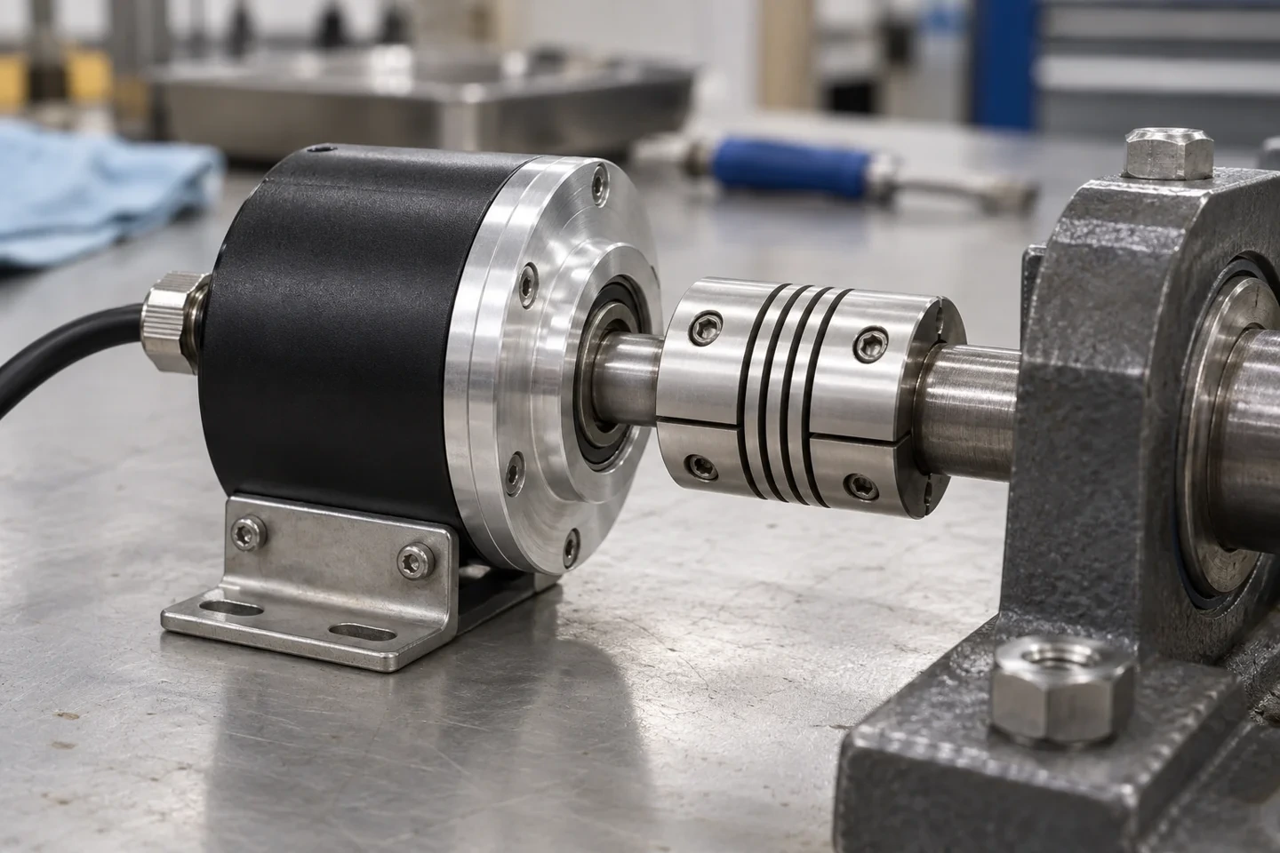
In the Framo Morat PoolCoverDrive technical data, the encoder type is Hall sensor.
In the Framo Morat PoolCoverDrive technical data, encoder resolution is 2 pulses per rotation.
In the Framo Morat PoolCoverDrive technical data, encoder output signals are 2 square wave signals in phase quadrature.
Use the following T&A AquaTop Control Box error and endpoint entries for the matching controller:
For AquaTop Control Box Version 1.2, encoder error 006 means no pulses or the wrong number of pulses; check wiring.
No-current error 007 combines no pulses and no motor current; the motor is not turning.
Position error 010 means the close and open positions overlap.
Overload error 005 means maximum motor current was exceeded; check the selected motor type.
In the AquaTop Control Box first-time configuration, the closed endpoint is programmed by pressing Program and Close simultaneously for approx 3 seconds.
In that AquaTop configuration, the open endpoint is programmed with Prog and Open simultaneously for approx 3 seconds.
In the Compass Pools Rollo Cover error table, NO PULSES indicates that the control board receives no encoder pulses.
In the Compass Pools Rollo Cover error table, for a maximum-current error, check whether the roller is blocked.
Record the displayed fault category before reprogramming open or closed endpoints.
SIREM sensor-error diagnostics: junction-box moisture, wiring and cable scraping
In the SIREM control-box diagnostic aid, a sensor error means sensor signals are not reaching the unit.
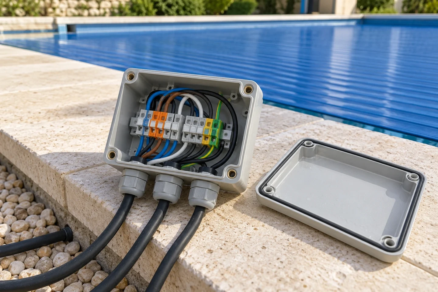
In the SIREM diagnostic checklist, the sensor-error checks include checking the junction box for moisture.
In the SIREM diagnostic checklist, the sensor-error checks include inspecting copper wires for corrosion or verdigris.
In the SIREM diagnostic checklist, the checklist checks for cut wires and pulls each connection to verify.
In the SIREM diagnostic checklist, the checklist checks that wires are screwed to the terminal block or clamped to the Wago connectors.
In the SIREM diagnostic aid, the sensor configuration setting distinguishes MIS 3 wires from COVEO 4 wires.
The SIREM diagnostic checks that the motor cable is not damaged and that the first blade is not scraping it.
On the SIREM COVEO control unit, the sensor-signal fault procedure calls for checking continuity of the motor output cable.
When inspection moves from low-voltage sensor leads to branch-circuit supply and bonding, use the automatic pool cover electrical requirements guide.
Post-power-interruption recovery and manual-mode limit precautions
Use the matching Cover-Pools or SIREM COVEO procedure when a travel-stop complaint follows a power outage or manual operation:
In the Cover-Pools auto-shutoff operation instructions, after a power interruption is restored, operating the control in the wrong direction can overrun the cover.
In that Cover-Pools auto-shutoff procedure, running the cover in the correct direction for a few feet after power restoration restores the shutoff sequence.
In that Cover-Pools configuration, the auto-shutoff control includes an adjustable amperage stop that turns off the motor if the cover meets significant resistance.
On the SIREM COVEO control unit, a power failure while the cover is closing produces a warning that initialization must be performed.
On the SIREM COVEO control unit, after initialization, manual mode allows movement beyond the limit switches.
On the SIREM COVEO control unit, from the closed position, do not unroll more than two full turns of the shaft; the manual warns of losing the limit switches and needing reinitialization.
On the SIREM COVEO control unit in manual mode, a sensor error displays a message but movement remains possible; correct the fault and restart.
Record whether the travel-stop complaint began immediately after a power outage or manual operation before reprogramming endpoints.
Mechanical cam limit calibration vs halfway-stop resistance checks
In the DEL Rollinside dry-pit limit-switch calibration section, electrical work must be performed by a qualified person wearing protective equipment.
For the DEL Rollinside MCA 120-MCA 250 motor, the manual directs checking the position of the limit-switch cams.
In the DEL Rollinside calibration procedure, choose the pool-open position carefully because it is saved as the starting position.
In the DEL Rollinside calibration procedure, the last control used when setting pool-closed must be close.
In the DEL Rollinside dry-pit manual, a blocked cover causes the motor to stop automatically.
In Automatic Pool Covers owner troubleshooting, dirt or debris in the tracks can cause a cover to stop halfway.
In Automatic Pool Covers owner troubleshooting, if pumping water off the cover does not resolve halfway stopping, a trained technician may need to adjust torque.
Keep mechanical cam calibration separate from track-debris and surface-water resistance checks in the service log.
Prepare the service handover record
Copy this diagnostic checklist into your service record and attach clear photos of the equipment labels and sensor mounting locations.
When inspection points to drive hardware replacement rather than sensor adjustment, continue to the automatic pool cover motor and mechanism replacement guide.
- Record the cover, motor and controller model labels from the equipment enclosure.
- Identify the installed stopping or position device: webbing magnet sensor, roll-up-tube rotation sensor, rotary limit switch, shaft pulse encoder or mechanical cam switch.
- Note whether the sensor stops the motor directly or operates a water-feature relay.
- Photograph the webbing magnet slit, guide-feed sensor bracket, rotary sensor disk, cam assembly or junction box.
- Record the failing direction and the measured stopping deviation from a fixed pool reference point.
- State whether the stopping position repeats consistently or shifts between cycles.
- Copy any displayed fault code, status-light color or warning message verbatim.
- Log any recent power interruption, manual-mode operation, track cleaning or surface-water removal.
Sources
- Cover-Pools: Mounting Rotary Switch to Opposite End
- Cover-Pools: T3 Evolution Automatic Pool Cover Owner’s Manual
- Latham: L0300 1601 Control Wiring Instructions
- Latham: L1031 3 Wire Motor Limit Control Instructions
- Latham: Mechanical Rotary Encoder Limit Switch
- Latham: Micro-Rotary Limit Switch Instructions
- Latham: Rotary Encoder Setup and Testing
- Framo Morat: PoolCoverDrive Technical Data
- T&A: AquaTop User Manual Control Box
- Compass Pools: Rollo Cover Installation Manual
- SIREM: Control Box Diagnostic Aid
- SIREM: COVEO Control Unit Technical Manual
- DEL: Rollinside dry-pit installation manual September 2024
- Automatic Pool Covers: Specification Book
Parent hub: Automatic pool cover parts