Updated October 2026
Top Track Automatic Pool Cover
A ladder, slide, or handrail that leaves less than 7 inches above the finished deck damages the cover when a top-track leading edge has to pass under it. A top-track automatic pool cover uses guides fastened on the walking surface of the deck, so the rail stays visible and the coping can stay in place.
A top-track automatic pool cover runs on guides mounted on the deck. Cover-Pools calls that family deck-mounted track and says new and existing pools can use it when the tracks run parallel on opposite sides. On document 800024, Universal and SnapTop are listed for existing decks, on the deck surface, in anodized aluminum. The Universal drawing is 11/16 inch high and 2-13/16 inches wide, and the SnapTop figure shows an extrusion with the same two callouts. Slim track is the smaller Step-Saver profile, so those callouts stay with the Universal and SnapTop figures. Coverstar's March 2015 deckmount guide prints a different set: the roll-up tube is 3 inches shorter than the track space, the tracks extend 18 inches past the waterline at each end, and the wheel assemblies need at least 7 inches of clearance under slides, ladders, and handrails. Keep each number with the page that prints it.
These locations sit under the pool cover track systems guide. A deck that is already finished is the setting on the existing-pool cover guide.
| Input or item | Typical value or source | Why it matters |
|---|---|---|
| Coverstar tube vs track space, 1004 step 1 | 3 in shorter. The printed example is a 20 ft track space and a tube of 19 ft 9 in | The tube spans the opening between the tracks |
| Coverstar track ends, steps 3 and 9 | 18 in past the waterline at the far end, and 18 in past the waterline at the mechanism | That extension is along the travel of the cover |
| Coverstar hardware clearance, step 2 | At least 7 in from the finished deck to the underside of slides, ladders, and handrails | The wheel assemblies and the leading edge pass in that gap |
| Coverstar anchors, step 14 | Drill at least 3 in deep. The top-track screw on the parts list is PFSM 12 x 1-3/4 | The hole is the purchase in the deck |
| Coverstar rope line, step 12 | A 1/2 in variance from straight is allowed on either side | A larger angle wears the guide feeds at the track end |
| Cover-Pools Universal drawing, 800024 | 11/16 in high and 2-13/16 in wide | Those callouts belong to the surface extrusion on that drawing |
| Cover-Pools square, recessed-mechanism drawing | Track space AB = CD, track length AC = BD, diagonals AD = BC | Opposite sides and diagonals are the square on that sheet |
| Cover-Pools end marks, same drawing | 2 ft beyond the pool at the far end, and a 1 ft minimum setback at the mechanism | Those marks belong to that drawing |
| Cover-Pools order limit, sizing page | Widths over 25 ft or lengths over 65 ft need factory approval. Maximum track space is 36 ft | A pool outside that limit is a factory question before the extrusions are ordered |
Surface guides, and the channel poured into the deck
Cover-Pools separates deck-mounted track from the guides that hide under coping. The track-systems page says new and existing pools can be covered with deck-mounted track when the tracks run parallel on opposite sides. An attached spa or steps outside the perimeter can still leave the pool covered on that page, provided the two tracks stay parallel.
On that page, SnapTop is a low-profile aluminum guide. Wheels or gliders carry the cover, and the screws are concealed. Universal track is also a low-profile aluminum guide, and it uses an adjustable dual-wheel assembly. Slim track is for spas, swim spas, and small pools with Step-Saver systems. Its install is similar to SnapTop, with concealed screws, and the page says it takes less deck space, is narrower, and has a smaller profile than SnapTop. Document 800024 repeats the existing-deck use for Universal and SnapTop, and it draws the Universal extrusion at 11/16 inch high and 2-13/16 inches wide. The SnapTop figure on the same page shows an extrusion with those same two callouts, and the caption under that figure reads "Universal track for spas and Step-Saver." Slim is the smaller profile named in the bullets, so the 11/16 inch and 2-13/16 inch callouts stay off the Slim line.
Flush track on the same options page is a different section. It is installed flush with the deck, inside a narrow channel poured into the deck, with a built-in rope diverter. The drawing labels 1-1/2 inch across the top of that channel and 3-1/2 to 4 inches for its depth. The options text recommends flush track for indoor use only. The recessed-mechanism page then sets flush track back 6 inches from the pool edge, while Universal track on that page may be mounted at the pool edge. That channel is the lowered guide. The recessed top track guide is the page for a rail set into the deck. A guide that has to hide under the coping is the undertrack automatic pool cover.
Rule of thumb: If deck clearance is under 7 inches from the finished surface to the underside of a ladder, slide, or handrail on the travel line, move that hardware before the Coverstar deckmount tracks are fastened. The March 2015 guide says the wheel assemblies and the leading edge need that gap to pass.
| Layout | Dominant failure mode and prevention |
|---|---|
| Coverstar splice left with a burr | The cover cuts on the joint. File every track end and round the edges before the splice. The guide says burr damage is easy, and the warranty leaves that damage out. |
| Coverstar screw standing above the track | The wheel path hits the head. Drill at least 3 in deep, start the PFSM 12 x 1-3/4 screws halfway, then finish them flush. The checklist requires every track screw tight and flush. |
| Coverstar rope more than 1/2 in off a straight line | The guide feeds wear at the end of the track. Move the mechanism until the rope variance on either side stays inside 1/2 in. |
| Cover-Pools track laid on a skimmer lid | The lid covers the skimmer. The recessed-mechanism drawing keeps the track off the top of that lid. |
| Flush track treated as a surface rail | The flush section is a poured channel, 6 in back from the pool edge on the recessed-mechanism page, with an indoor recommendation on the options sheet. Universal and SnapTop are the surface guides. |
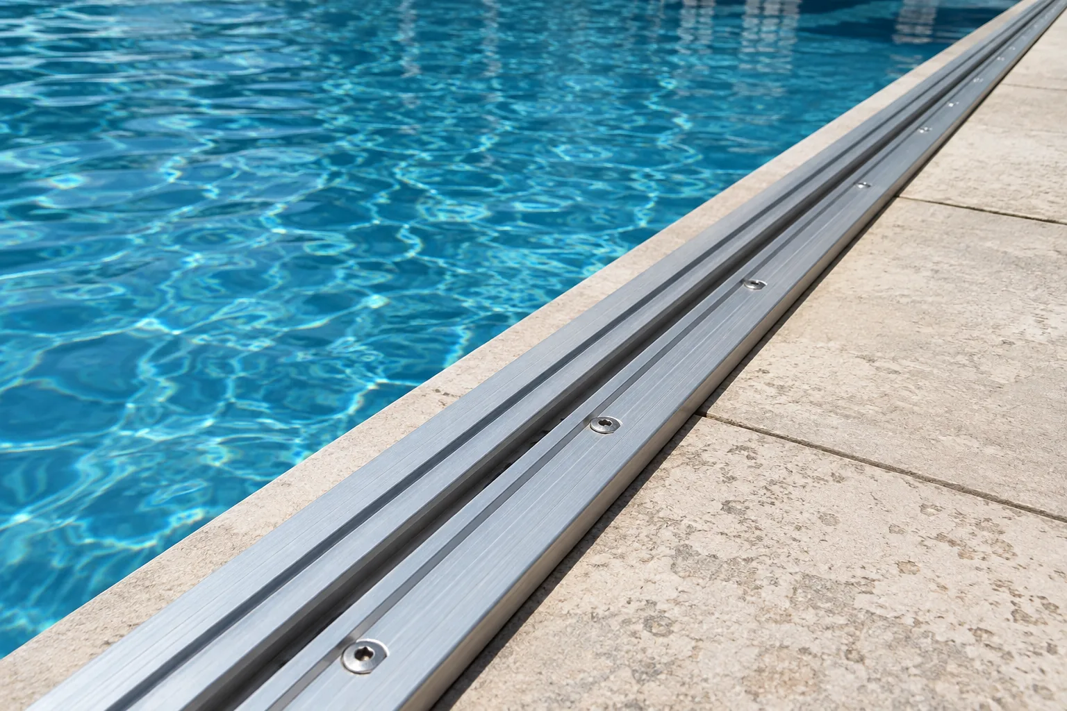
Coverstar's deckmount guide prints the travel lengths
The Coverstar automatic safety cover deckmount guide, copyright 2007, dated March 2015, version 3.1, is the surface procedure used here. The parts list says it is typical for most pools up to 20 feet by 40 feet, and that parts vary for longer or wider pools and for the specific order. It names X0656 as standard top track, A1565 as the wheel assembly for standard top track, and H0334 as screw PFSM 12 x 1-3/4 for top track. It also names X0001 as a 6 inch aluminum roll-up tube and A0797 as a tube insert for a 6 inch tube. That 6 inch name is the parts-list tube. The 3 inch shortening is a separate length rule.
Step 1 says the roll-up tube should be 3 inches shorter than the track space. The printed example is a tube of 19 feet 9 inches for a track space of 20 feet. Track space in that sentence is the opening the tube spans, between the tracks.
Steps 3 and 9 set the other direction. Extend the tracks 18 inches past the waterline. With the tracks already at least 18 inches past the waterline at the opposite end, cut them so they extend 18 inches past the waterline at the mechanism end. Those 18 inch marks run along the cover's travel. The tube length stays on the 3 inch rule.
Step 2 requires at least 7 inches of clearance from the top of the finished deck to the bottom side of slides, ladders, and handrails, so the wheel assemblies and the leading edge can pass under them. Step 14 drills through the pre-drilled holes at least 3 inches deep, sets plastic anchors, and fastens the track screws halfway. Later, during the rope steps, every track screw is finished flush with the top of the track. The checklist repeats that the screws are tight and flush, that pulleys sit flush against the end of the track, and that every track end is filed.
Step 12 allows only a 1/2 inch variance from straight on either side of the rope line from the track to the pulley. The checklist says an excessive rope angle wears the guide feeds at the end of the track, and it leaves 8 feet of rope on the rope reel. The cover-fabric steps say the cut ropes should be at least 8 feet long. That spare belongs to this guide.
The same guide requires the system to be bonded to meet the National Electrical Code. Bond both tracks to the mechanism with a #8 solid copper bond wire, bond metal longer than 4 inches, and mount the key switch in an all-weather box where the whole pool is visible. The guide assigns the conduit to the builder. The circuit diagram stays in that guide.
A cover roller in the fabric steps is installed 2 to 3 inches behind the guide feed. The first two fabric screws on the tube are 3 inches from the end of the tube, then every 2 to 3 feet, with no folds. Those are fabric-attachment lengths on this guide. Track height and width stay on the Cover-Pools drawings.
Each drawing keeps its own square
Cover-Pools 800024, on the page for a recessed mechanism with Universal, SnapTop, or Flush track, says the requirements of a recessed mechanism with a deck-mounted track match the undertrack requirements on the previous page of that document. The drawing then prints its own square:
- Track space: AB = CD
- Track length: AC = BD
- Diagonals: AD = BC
- The note beside the pool also prints AD = CB, the same diagonal pair with the letters reversed
- Tracks are squared to the box or the mechanism
- The motor-side marks beside that note are GE = 6 ft, GF = 8 ft, and FE = 10 ft
The far end of that drawing is marked 2 feet beyond the pool. The mechanism end is marked with a 1 foot minimum setback. Universal track may be mounted at the pool edge. Flush track must be set back 6 inches from the pool edge. The shaded band at the mechanism is labeled excavation. The 18 inch, 16 inch, and 36 inch arrows on that band are excavation marks. They are excavation on this drawing, and they are separate from Coverstar's 18 inch extension past the waterline.
The sheet says the diagrams are general information and that the installation instructions for the unit govern. The three locations side by side are on the undertrack, top track, and recessed track comparison.
Coverstar's layout step measures track space, track length, and the diagonals, and it says the tracks must form a perfect square. The next line says lengths, widths, and diagonal dimensions must be equal to each other, or the system will not operate properly. The later checklist, on the same guide, says an inch or two out of square is ordinary for operation of that cover, because the size of the fabric roll and changes in operating conditions move the alignment as the cover runs. Use the sentence that matches the moment in that guide: the layout step is the setup check, and the checklist is the later note about fabric alignment. The Cover-Pools rectangle on 800024 stays with 800024. The Coverstar allowance stays with the 2015 checklist.
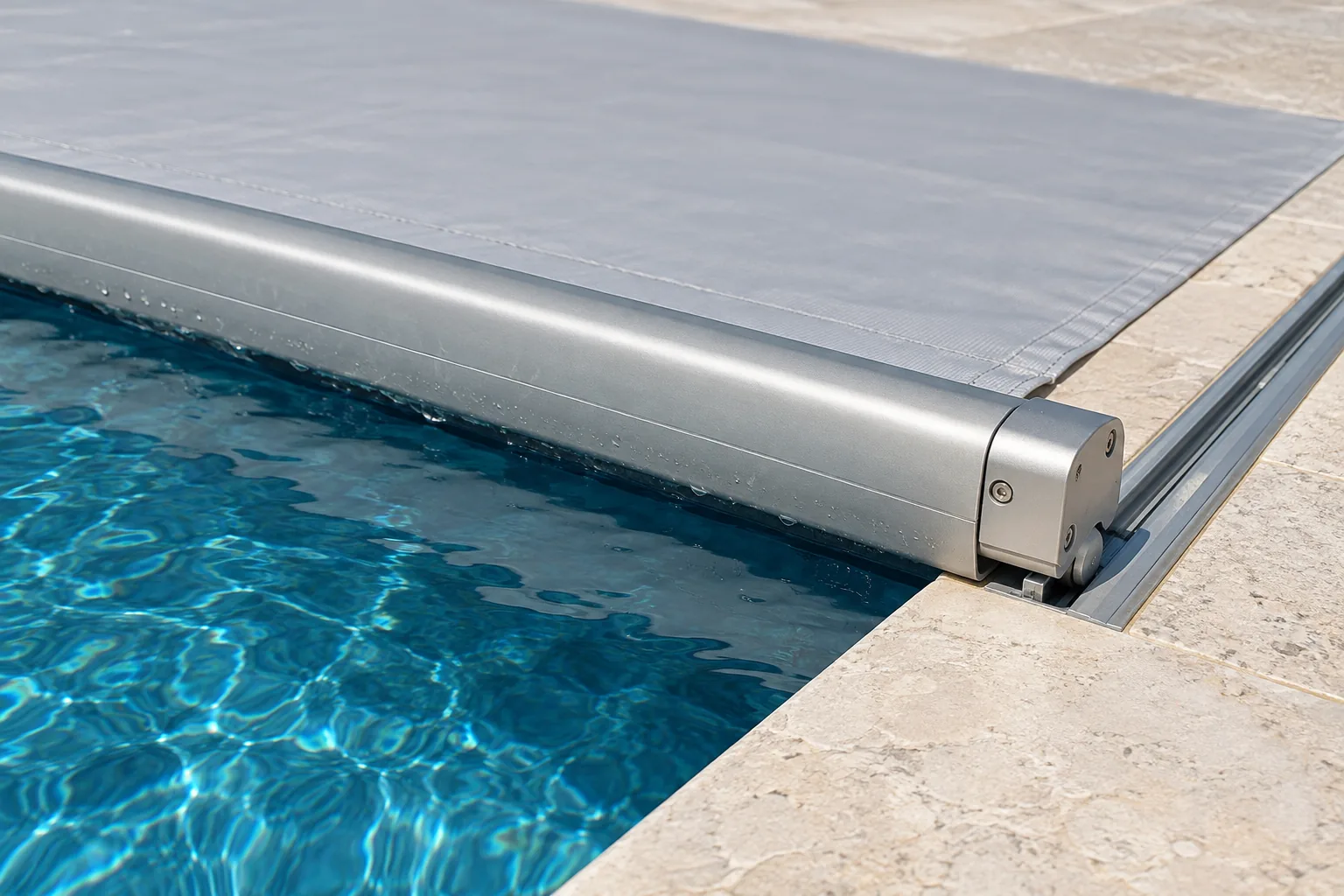
Worked example: the 20 foot track space
The Coverstar deckmount guide states both the rule and the example. The roll-up tube is 3 inches shorter than the track space. For a 20 foot track space, the tube is 19 feet 9 inches.
Tube length = track space - 3 in
Worked example. Track space = 20 ft = 240 in. Tube length = 240 - 3 = 237 in. 237 in = 19 ft 9 in, which is the length printed in the guide.
Order the tube from the track space after the guides are located. If the tracks later move because a ladder sat inside the 7 inch clearance, or because a skimmer lid was on the line, this length no longer matches the pool. The 18 inch extensions past the waterline run along the travel. The subtraction uses track space only. The 6 inch aluminum roll-up tube on the parts list is the tube that list names. That name sits beside the 3 inch shortening, and both sit apart from any housing size.
The Cover-Pools sizing page computes cover area as track space times pool length, and it says widths over 25 feet or lengths over 65 feet require factory approval, with a maximum track space of 36 feet. Its pricing sketch assumes the motor mechanism is one foot from the pool edge. That one foot is a pricing basis on the sizing page. The 1 foot minimum setback is a layout mark on the recessed-mechanism drawing. Read the heading on the sheet before treating them as one rule.
The work a finished deck still leaves
Cover-Pools lists Universal and SnapTop for existing decks, installed on the deck surface. Leaving the coping in place is the reason those lines exist. The work that remains is on the walking surface.
The Coverstar guide needs a hole at least 3 inches deep for each track anchor, screws finished flush, and 7 inches of clear air under any slide, ladder, or handrail on the travel line. A deck that cannot hold that hole is a deck repair. A rail inside that 7 inch gap has to move, or the guide says the cover system is damaged. A burr left at a splice is fabric damage the same guide places outside the warranty. The checklist also wants 8 feet of rope left on the reel, pulleys flush to the track end, and the mechanism at a right angle to the track.
Cover-Pools adds its own stop lines. The deck-mount paragraph applies when the tracks run parallel on opposite sides. The track stays off the top of a skimmer lid. Widths over 25 feet or lengths over 65 feet, and any track space over 36 feet, go back to the factory before the extrusions are ordered. The parts list on the Coverstar guide is typical through 20 feet by 40 feet. A longer or wider pool changes that list.
Prices for the hours, the anchors, and the moved ladder sit outside this page. The bill is the visible rail, the anchor depth, and the hardware that has to clear 7 inches. A guide that has to disappear under the coping is a different document, on the undertrack page.
Common questions
Does the rail show on the deck?
Yes. Cover-Pools installs Universal and SnapTop on the deck surface. SnapTop conceals the screws and still leaves the aluminum guide on the deck. Flush track is the channel poured into the deck, set back 6 inches from the pool edge on the recessed-mechanism drawing.
Do the 18 inch and 2 foot extensions describe the same end of the pool?
No. Coverstar's March 2015 deckmount guide extends the tracks 18 inches past the waterline at the far end and 18 inches past the waterline at the mechanism. Cover-Pools 800024, on the recessed-mechanism drawing for Universal, SnapTop, or Flush track, marks 2 feet beyond the pool at the far end and a 1 foot minimum setback at the mechanism. The shaded excavation on that drawing has its own 18 inch, 16 inch, and 36 inch arrows. Use the sheet that matches the mechanism on the deck.
Sources and method
Updated October 2026. This page explains top track from public Cover-Pools and Coverstar documents. It is an independent account of those documents. Field dimensions for a given pool stay with the installation instructions for that mechanism.
- Cover-Pools, Track Systems, fetched 18 October 2026 from https://www.coverpools.com/pool-professional/components-and-technology/track-systems-original/. Deck-mounted track for parallel runs, SnapTop with concealed screws, Universal with an adjustable dual-wheel assembly, Slim track for Step-Saver, and flush track poured into the deck.
- Cover-Pools, General Installation Overview, 800024, fetched 18 October 2026 from https://www.coverpools.com/wp-content/uploads/2016/11/800024-PUBL-GENERAL-INSTALLATION-OVERVIEW.pdf. Universal and SnapTop drawings, the flush-track channel, the recessed-mechanism square, the 2 foot and 1 foot end marks, and the sizing-page limits of 25 feet, 65 feet, and 36 feet. The sheet says the diagrams are general information.
- Coverstar, Automatic Safety Cover Deckmount System installation guide, document 1004, copyright 2007, March 2015 version 3.1, fetched 18 October 2026 from https://ellispoolcovers.com/wp-content/uploads/2020/05/1004.pdf. The 3 inch tube rule, the 20 foot example, the 18 inch waterline extensions, the 7 inch clearance, the 3 inch anchor depth, the 1/2 inch rope variance, and the PFSM 12 x 1-3/4 top-track screw.
The local industry library returned no pool-cover track manual for this topic. Cached searches for top track, pool cover, and Cover-Pools returned no stored result pages, so no competitor page was purchased or used as a fact source.