Updated November 2026
Hydraulic Automatic Pool Cover Hose Run Pressure Drop and Relief Valve Bypass Calibration
A hydraulic automatic pool cover separates the electric pump and fluid reservoir from the wet cover pit by sending pressurized oil through buried supply and return lines to the pool-end drive motor. When hose runs are long or cold morning temperatures thicken the fluid, line backpressure combines with motor load at the pump manifold and can cause the bypass relief valve to open early, slowing or stalling the cover mid-pool. Review our hydraulic automatic pool covers overview and follow the hose sizing, fluid viscosity, and brand-specific relief valve calibration steps below before adjusting bypass pressure.
Laminar pipe-flow friction, fourth-power hose diameter scaling, and conduit bend radius
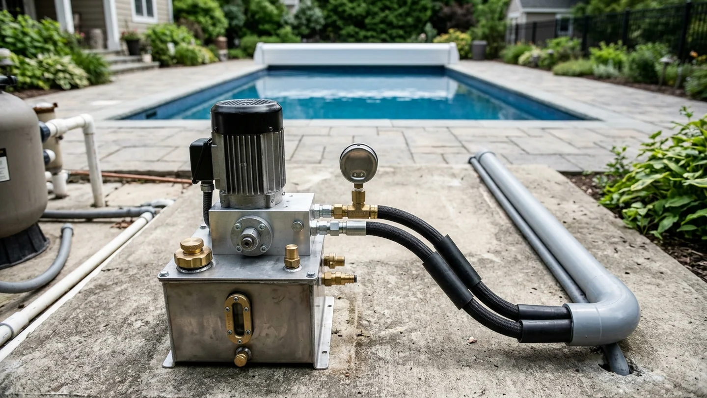
When a hydraulic power pack sits in an equipment room away from the pool, pressurized oil must travel through both the supply hose and the return hose to drive the roller mechanism in the cover housing, as outlined in our hydraulic pool cover system design guide.
In Engineering ToolBox pipe-flow regime definitions, pipe flow is laminar when Reynolds number Re < 2300 and transient when 2300 < Re < 4000.
For laminar flow in a circular pipe of diameter D c, the friction factor is inversely proportional to the Reynolds number alone (f D = 64 / Re).
In laminar pipe flow, pressure loss per unit length is Delta p / L = (128 / pi) * (mu * Q / D_c^4), inversely proportional to the 4th power of pipe diameter.
In the Cover-Pools Hydraulic Pump Installation Manual, the Cover-Pools hydraulic pump system is supplied as 120v 1-1/2hp #050275 or 220v 1-1/2hp #050276.
In the Cover-Pools Hydraulic Pump Installation Manual, Cover-Pools hydraulic drive motor #050116 has a displacement of 5.9 cu in and rated speed of 39 rpm.
In the Cover-Pools Hydraulic Pump Installation Manual, Cover-Pools hydraulic hoses must be 3/8" or larger with a minimum rating of 2000 psi, and hose runs longer than 100' must use 1/2" hose or larger.
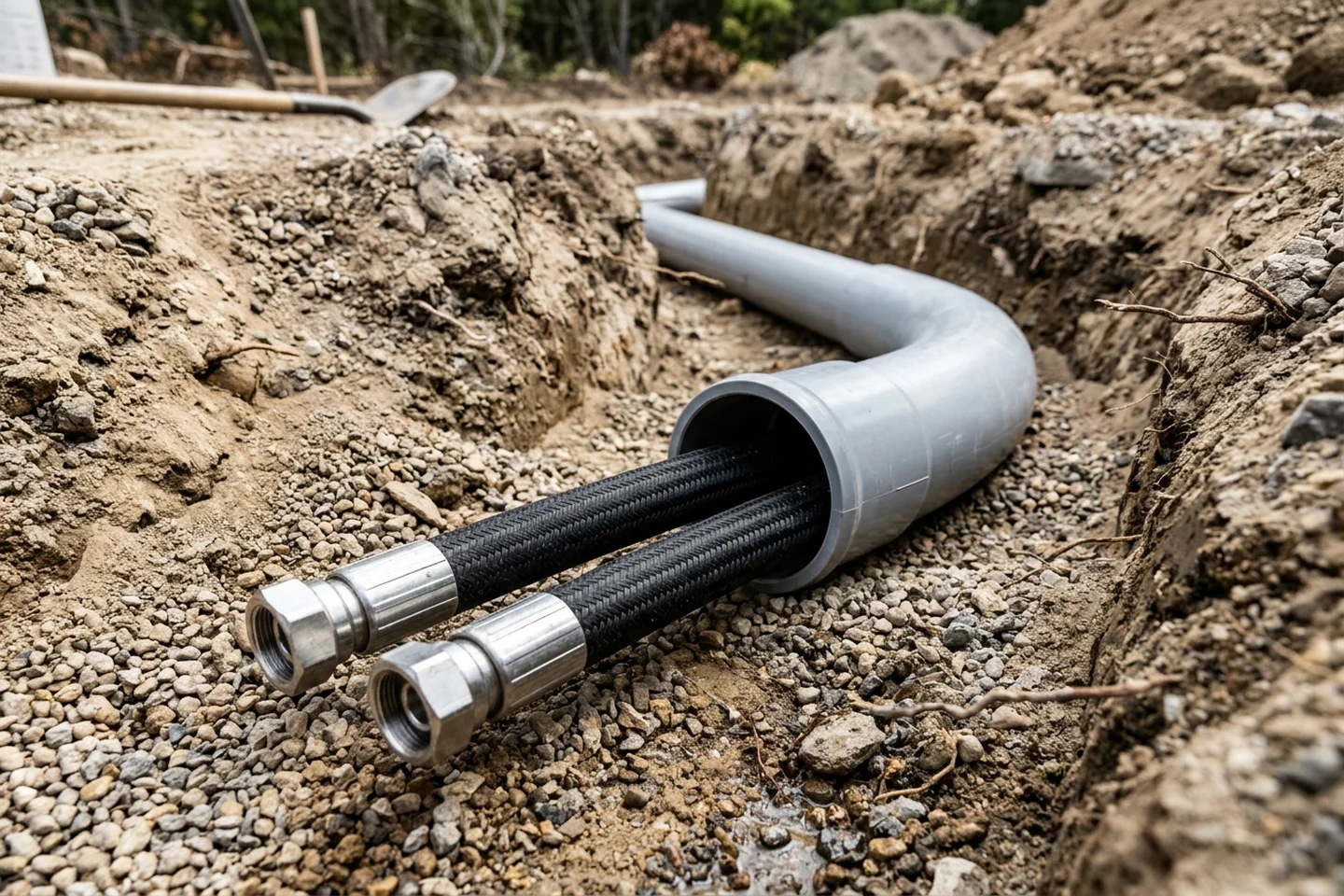
In the Cover-Pools General Installation Overview, the cover housing diagram specifies two 1/2" hoses with large sweeping bends for hose runs over 80'.
In the Cover-Pools Parts Guide, part 150026 is Hydraulic Hose 3/8 (requiring 2 each 080051 per hose) and part 050181 is Hydraulic Hose Assembly 1/2 sold per foot.
In the Cover-Pools Hydraulic Pump Installation Manual, Cover-Pools requires running 2 hydraulic hoses through Polyethylene or PVC pipe conduit with a minimal ID of 3" and large sweeping bends on all 90º degree turns.
In the Aquamatic Hydramatic Undertrack Installation Manual, Aquamatic Hydramatic specifies 3/8 inch inside diameter non-conductive poly-braided hydraulic hose with a working pressure of 1250 to 2250 psi and #6 - JIC 37 female swivel fittings.
In the Coverstar Parts Catalog, hydraulic drive motors include A0698 Hydraulic Motor 8 cu in 30 rpm sqft > 800 with hardware, A0699 Hydraulic Motor 10 cu in sqft > 2000 with hardware, and A0700 Hydraulic Motor 12 cu in (Special order only) with hardware.
Upsizing hose inside diameter on long equipment-pad runs and pulling both lines through wide-radius conduit bends keeps parasitic line friction from consuming available pump pressure.
Hydraulic fluid viscosity grades, hose fill allowances, and cold-morning backpressure
Because laminar line pressure loss scales directly with fluid dynamic viscosity, oil grade and morning ambient temperature (via viscosity) plus hose length and diameter affect manifold pressure at the pump; separately, add the manufacturer hose-fill volume so the reservoir is not starved.
In Fluid Power World cold-weather hydraulic maintenance guidance, although a hydraulic system will function between 10-1,000 centistokes (mm²/s), the ideal operating viscosity might be 16-36 centistokes, for example.
In Fluid Power World cold-weather hydraulic maintenance guidance, anti-wear hydraulic oil is rated at 40°C (105°F), but AW32 viscosity exceeds 1,000 centistokes at freezing.
In the ISO industrial lubricant viscosity classification table, ISO VG 32 has a kinematic viscosity bracket of 28.8 to 35.2 (mid-point 32.0), and ISO VG 46 has a bracket of 41.4 to 50.6 (mid-point 46.0).
In the Castrol Transmax ATF DX III Multivehicle Product Data Sheet, Castrol Transmax ATF DX III Multivehicle has a kinematic viscosity of 35 mm²/s at 40C, 7.2 mm²/s at 100C (ASTM D445), and a Viscosity Index of 175 (ASTM D2270).
In the Castrol Transmax ATF DX III Multivehicle Product Data Sheet, Castrol Transmax ATF DX III Multivehicle has a Brookfield viscosity at -40C (75W) of 16500 mPa.s (cP) per ASTM D2983 and a Pour Point of -45 °C per ASTM D97.
In the Sinclair ATF Dexron-III/Mercon Product Data Sheet, Sinclair ATF Dexron-III/Mercon has a Specific Gravity of 0.8603 at 60°F (15.6°C) per ASTM D4052 and Viscosity at 40°C of 35.67 cSt per ASTM D445.
In the Cover-Pools Hydraulic Pump Installation Manual, Cover-Pools specifies type F or Dextron Transmission fluid, adding 1½ to 2 quarts of fluid for every 50' of hose.
In the Aquamatic Hydramatic Undertrack Installation Manual, the Aquamatic Hydramatic reservoir holds approximately 3 1/2 quarts of fluid with the hydraulic hoses holding an additional one-quart per each 35 ft of hose.
In the Latham Hydraulic Pump Installation Instructions, the Latham hydraulic pump specifies ISO 46 hydraulic fluid (or Dextron III if unavailable) and approximately 3 quarts of oil for the tank.
In the Latham Hydraulic Pump Installation Instructions, Latham hydraulic lines require approximately 1 pint of fluid for each additional 10 feet of hose run.
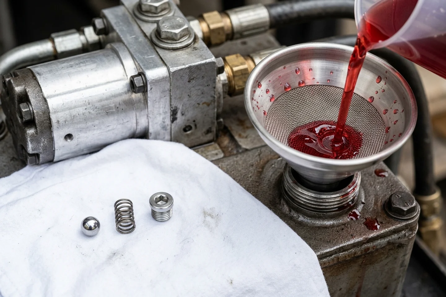
In the Latham Hydraulic Pump Installation Instructions, Latham specifies filling the hydraulic power pack using a funnel with an approx. 60 micron filter screen.
In the Aquamatic Hydramatic Owner's Manual, Aquamatic warns not to run the pool cover below 40*F because cold operation can create cold cracks in the vinyl.
Matching the manufacturer fluid specification and accounting for additional hose volume prevents cold-morning viscosity spikes and reservoir starvation.
Direct-acting relief valve pressure override and brand-by-brand bypass calibration
Unlike electric drive mechanisms that rely on mechanical torque limiters as covered in our slip-clutch torque calibration guide, hydraulic power packs use spring-loaded relief valves at the pump manifold to bypass oil back to the reservoir when circuit pressure reaches the preset threshold.
In Power & Motion Tech Chapter 9 on pressure controls, direct-acting relief valves are not normally used on industrial hydraulic systems, except for those with flows under 3 gpm, and as pilot control devices.
In Power & Motion Tech Chapter 9, direct-acting relief valves open partially at about 150 psi below set pressure; as the poppet opens it compresses the spring and pressure rises with bypass flow.
In Power & Motion Tech Chapter 9, with a direct-acting relief valve set to 1500 psi at 10 gpm, it is very possible that some fluid will start to pass when pressure is as low as 1350 to 1400 psi.
In the Cover-Pools Hydraulic Pump Installation Manual, installers must use Loctite hydraulic thread sealant or Teflon paste on the hydraulic gauge fitting and must not use Teflon tape.
In the Cover-Pools Parts Guide, Cover-Pools lists 050117 Hydraulic Pressure Gauge and 090012 Loctite Sealant for pressure gauge threads.
In the Cover-Pools Hydraulic Pump Installation Manual, average operating pressure on a Cover-Pools hydraulic system is typically between 300 to 800 psi, while large pool covers may operate up to 1000 psi or higher.
In the Cover-Pools Hydraulic Pump Installation Manual, if a Cover-Pools cover stalls, jumps, or runs jerky, the bypass valve setting may need adjustment; it is factory set to stall at 1000 psi.
To set the Cover-Pools bypass valve, open or close the pool cover to a fully stalled position and adjust the set screw so the gauge reads about 250 psi greater than the highest observed reading.
In the Aquamatic Hydramatic Undertrack Installation Manual, Aquamatic Hydramatic uses two interconnected hydraulic motors with an operating pressure of 600-800 psi.
In the Aquamatic Hydramatic Compact Drive brochure, the Aquamatic Hydramatic Compact drive specifies a normal working pressure of 800 psi (40-56 bar).
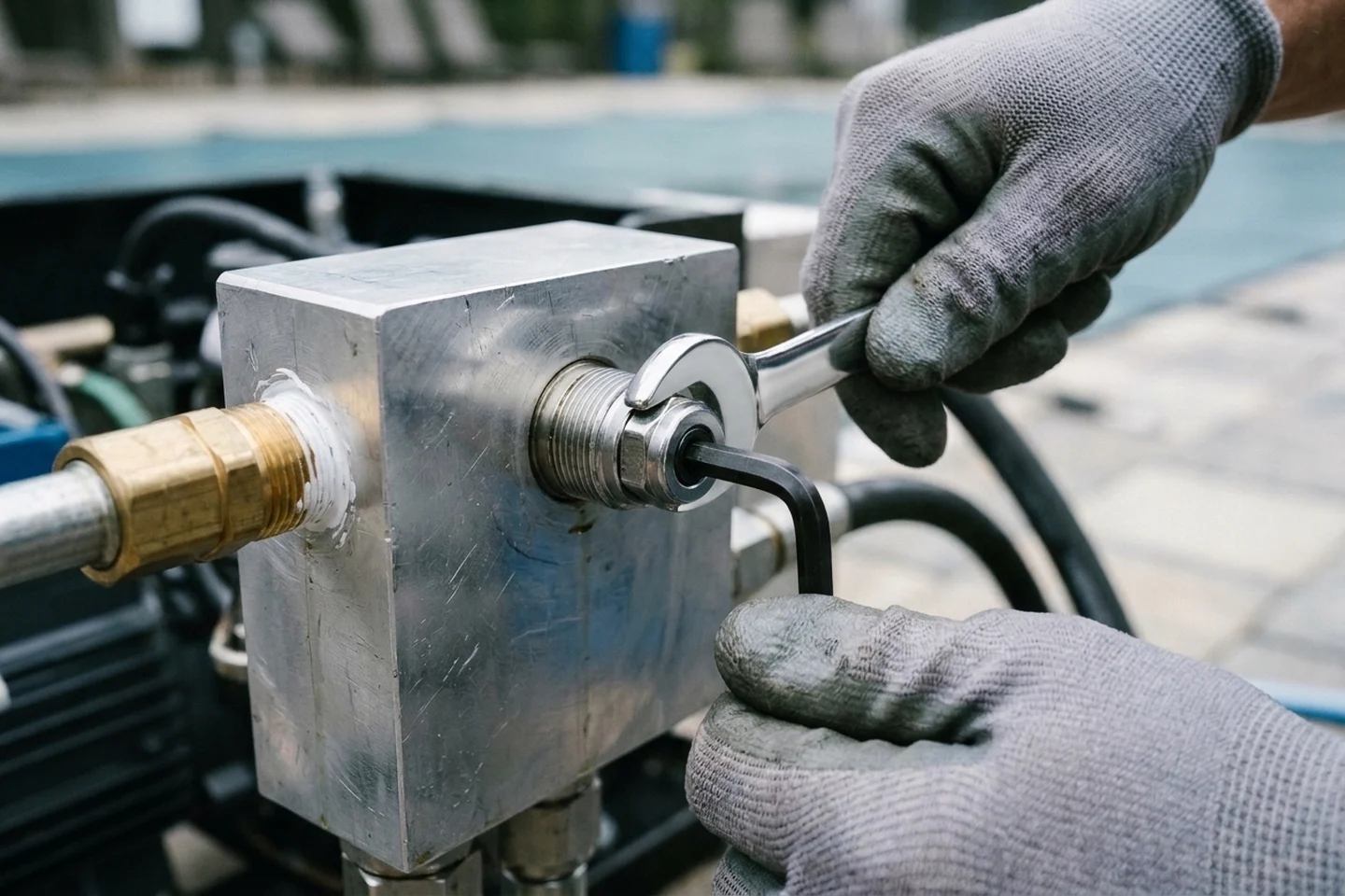
On the Aquamatic powerpack, loosen the 9/16" nut with a socket and turn the 3/16" Allen set screw in to increase pressure.
In the Aquamatic Hydramatic Undertrack Installation Manual, Aquamatic specifies making only small relief valve adjustments at a time of 1/4 to 1/2 turns and checking that the cover operates in both directions without hesitations.
In the Latham Hydraulic Pump Installation Instructions, the Latham hydraulic unit bypass valve is covered by a cap removed with a 7/8" wrench and is preset at the factory to 600 pounds pressure.
On the Latham unit, use the #3 flat head screwdriver to turn the pressure relief screw counter clockwise until the cover stalls, then clockwise until the cover runs smoothly.
After the Latham cover runs smoothly during bypass calibration, tighten the pressure relief screw ½ turn more and tighten the cap.
In the Coverstar Dealer Manual, Coverstar hydraulic unit bypass valves are preset at the factory to 600 pounds pressure.
To adjust a Coverstar bypass valve, use an 11/16" wrench to loosen the lock nut on the top bypass and insert a 3/16" Allen wrench.
Setting the relief valve margin just above normal running load keeps the poppet seated past the partial-bypass cracking band without over-pressurizing the cover drive.
Isolating surface water weight, bypass debris, flange check valves, air pockets, and voltage drop
Before increasing bypass pressure on a stalling cover, technicians isolate surface water weight, valve seat debris, directional check valve contamination, air entrainment, and electrical supply drop—or proceed to automatic pool cover motor and mechanism replacement if the pit drive hardware is seized.
In the Aquamatic Hydramatic Owner's Manual, one cubic foot of water weighs approximately 62 lbs, so 1 inch of water on a 20 ft by 40 ft cover equals about 4000 lbs (two tons) of weight.
To clear contamination in a Latham bypass valve, loosen the screw while keeping at least 3 full turns in the threaded hole and run the power pack for 30 seconds.
If a Coverstar powerpack works in only one direction, inspect the two check valves above each bypass valve using a 7/32" allen wrench to remove the cap, spring, and ball bearing.
In the Aisoar Hydraulic air bleeding guide, air in hydraulic system symptoms include jerky actuator movement, inconsistent cycle times, whining noise near the pump, foamy reservoir oil, and pressure fluctuation.
During Cover-Pools initial operation, turn the key switch to Open or Close and run the hydraulic system for 3-5 minutes without reversing direction.
When air has been removed from the Cover-Pools hydraulic system, fill the reservoir to 1" below the fill hole and install the breather cap.
If voltage at the Coverstar hydraulic powerpack drops more than 5 % while the system is running, the system is underpowered and requires a licensed electrician to check the wiring.
Pumping standing rain off the cover, flushing debris from the bypass and check valves, purging air in a single direction, and verifying supply voltage under load prevents misdiagnosing external faults as relief valve drift.
Field commissioning and troubleshooting record
Record the following site and manifold observations in the commissioning file before adjusting the relief screw or dispatching a hydraulic repair visit:
For equipment room layout, conduit trenching, and mechanical drive comparisons, continue to our hydraulic automatic pool covers hub, hydraulic pool cover system design guide, slip-clutch torque calibration guide, and automatic pool cover motor and mechanism replacement guide.
- Measure the distance from the remote hydraulic power pack to the pool cover housing pit and note the conduit diameter and bend geometry.
- Record the hydraulic hose inside diameter and fitting style installed on the supply and return lines.
- Log the fluid type in the reservoir, the morning ambient temperature when stalling occurs, and whether the reservoir oil appears clear or foamy.
- Verify that all standing rainwater and leaf debris have been removed from the cover surface and anodized guide tracks before testing travel.
- Record the manifold pressure gauge reading during normal open and close travel alongside the fully stalled gauge reading.
- Note whether hesitation occurs in both directions or in a single direction only, and log the supply voltage under running load.
Sources
Manufacturer installation manuals, lubricant product data sheets, and fluid-power engineering references cited in this guide:
- Cover-Pools Incorporated — Hydraulic Pump Installation Manual, General Installation Overview, and Automatic Pool and Spa Covers Parts Guide
- Aquamatic Cover Systems — Hydramatic Automatic Swimming Pool Cover Owner Manual, Undertrack Installation Manual, and Compact Pool Cover Drive Brochure
- Latham Pool Products and Coverstar — Hydraulic Pump Installation Instructions, Automatic Safety Covers Dealer Manual, and Parts Catalog
- Castrol Transmax ATF DX III Multivehicle and Sinclair ATF Dexron-III/Mercon Product Data Sheets
- Power and Motion Tech and Fluid Power World — Relief and Unloading Pressure Controls and Cold-Weather Hydraulic Maintenance Guides
- Engineering ToolBox, Wikipedia, and Aisoar Hydraulic — Darcy-Weisbach and Hagen-Poiseuille Laminar Pipe Flow and Hydraulic Air Bleeding References
Parent hub: Hydraulic automatic pool covers