Updated October 2026
Low-Voltage Pool Cover Controls vs Motor Power: What to Confirm
Ordering a replacement switch from a partial label can damage the controller or stall the electrician on site. Confirm the motor nameplate, control board architecture, feeder breaker rating, and vault junction hardware from the matched manufacturer manual before anyone disconnects a wire.
In automatic pool cover systems, "low voltage" almost always describes the operator signal circuit between a poolside key switch or keypad and an intermediate control board—not the power driving an electric cover motor. Standard electric cover motors in documented Cover-Pools, Latham/Coverstar, and Automatic Pool Covers, Inc. (APC) manuals still run on 110VAC to 120VAC single-phase line power supplied through a dedicated 15-amp or 20-amp GFCI-protected circuit, and connections inside the recessed cover housing still require elevated weatherproof enclosures, watertight fittings, and unobstructed vault drainage.
This guide is for pool owners and builders preparing the technical packet for a licensed electrician and cover technician before replacing a controller or pre-wiring a cover vault. For high-level project provisions during early design, start with automatic pool cover electrical requirements and the automatic pool cover installation hub. This page does not provide universal 24V or IP68 wiring recipes, cross-brand wire-color splicing instructions, or local electrical code sign-off.
| System element | What to confirm before work starts | Example from published manuals (model-specific) | Why it matters for trade handoff |
|---|---|---|---|
| Power supply & feeder | Dedicated GFCI breaker rating, line voltage, and conduit path to the control board or switch | 110VAC–120VAC on a dedicated 15A GFCI breaker (Latham 1403.pdf; Cover-Pools 800024) or 120VAC 20A GFCI breaker (APC DO0392) |
Confirms what line power enters the system before anyone opens a box |
| Motor assembly | Motor nameplate voltage, horsepower, phase, wire count, and direction leads | 110VAC–120VAC, 3/4 HP, 3-wire reversible motor with Red/Blue directional leads and White neutral (Latham 1403.pdf) or 1/4 HP 115VAC motor on older units |
Prevents assuming a low-voltage switch runs a low-voltage motor |
| Control signal & board | Whether the poolside switch switches 120VAC directly or sends a low-voltage signal to an intermediate board | Cover-Pools Key Switch 120V (high-voltage only) vs Key Switch 5v (three 18 AWG wires to Auto-Shutoff board); APC 8-conductor × 22 AWG harness to Sensor Motor Adapter (DO 0248) |
Determines conductor count, wire gauge, and whether a separate control module sits between the switch and motor |
| Wet-vault & protection hardware | Enclosure location (outside vault vs highest point inside vault), watertight flex conduit, vault drain, and bonding | Motor splices in an all-weather box mounted as high as possible in the cover box with watertight connections (Latham 1403.pdf); 36" waterproof flex conduit with 1/2" NPT watertight connector and 3" housing drain (Cover-Pools 800024) |
Low-voltage poolside controls do not remove 110V–120V wet-zone exposure inside an electric motor vault |
Why does a "low-voltage key switch" not mean a low-voltage cover motor?
A product title such as "Low Voltage Key Switch" only describes the operator interface on the wall, not the electrical load at the roller drum. When a system uses a low-voltage key switch, keypad, or wireless receiver, an intermediate control module—such as an auto-shutoff amp-limiter board, motor control board, or sensor motor adapter—steps down voltage for the poolside signal wires while still switching 110VAC or 120VAC line power to the electric drive motor.
Published manuals from three major manufacturers show how both architectures exist side by side:
- Cover-Pools (
800024-PUBL-GENERAL-INSTALLATION-OVERVIEW.pdf, printed pages 5–6 and 16–17;800235-T4-Versa-OWNERS-MANUAL.pdf, printed page 16): The same 3/4 HP waterproof electric motor powered by a dedicated 120VAC 15-amp GFCI breaker can be wired in two different ways. Standard equipment uses a 3-wireKey Switch 120V(markedhigh-voltage onlyon page 17) that routes line-voltage directional wires (Neutral, Dir 1, Dir 2, Ground) directly toward the motor's 36-inch waterproof flex conduit. When an Auto-Shutoff board is added, the poolside control becomes aKey Switch 5vusing three 18 AWG low-voltage wires—or a wiredCoverLinkcontrol pad using four 18 AWG wires—landed on the Auto-Shutoff board, while 120VAC power still runs from the Auto-Shutoff board through high-voltage conduit into the cover housing. On page 16 of the T4 Versa manual (800235 REL-0001), the diagram explicitly labels the harness between the Auto-Shutoff/Motor Control Board and the CoverLink Receiver as(LOW VOLTAGE WIRES)and the motor and supply leads on the board as(HIGH VOLTAGE WIRES). - Automatic Pool Covers, Inc. (
DO0392-Spec-Book-2025-V2-1.pdf, printed pages 56 and 58–60): In APC's directPowerTouchtouchpad setup (DO-0325, page 56), three 12 AWG conductors from a dedicated 120VAC 20-amp GFCI breaker feed the touchpad junction box, and four 12 AWG wires carry switched 120VAC power back to the high-voltage junction box in the mechanism housing. In APC's low-voltage key switch setup with a Sensor Motor Adapter (SMA KA 0384,DO 0248, pages 59–60), a low-voltage conduit carries a 5-conductor 18–22 GA stranded cable from the poolside switch to a low-voltage junction box and an 8-conductor × 22 AWG harness into the SMA—while a separate high-voltage PVC conduit still carries three 12 AWG conductors from a dedicated 120VAC 20-amp GFCI breaker into the recessed housing to drive the 120VAC 3/4 HP motor. - Latham / Coverstar (
1403.pdf, Rev. 1/15/2013): The wiring sheet for110VAC 3 WIRE MOTOR USING THE TOUCHPAD POOL COVER CONTROLLER A2463/A2469routes 110VAC from a 15-amp GFCI breaker (H(BLK),N(WHT),GND(GRN)) to the controller in a standard-depth single-gang all-weather box, and sends switchedCVR(RED),UNCVR(BLUE),N(WHT), andGND(GRN)conductors to the all-weather box inside the cover box for the 3-wire 3/4 HP motor.
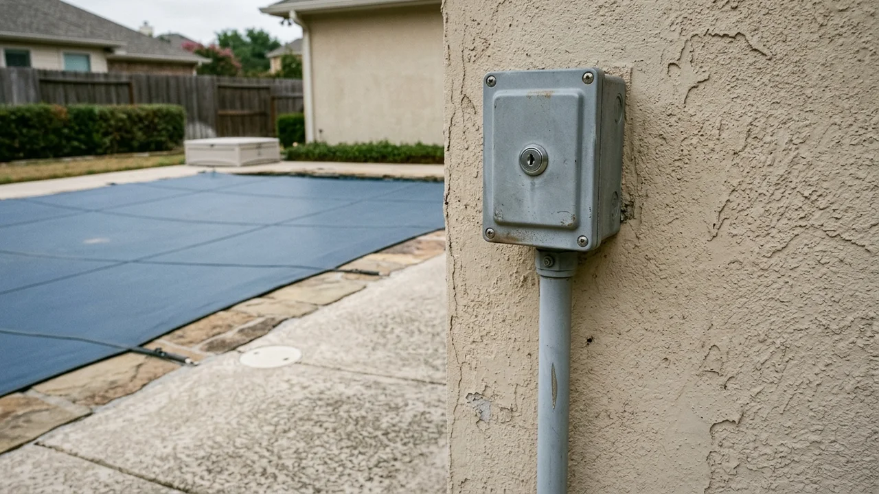
Takeaway: Never order a replacement switch or pull new conduit based on the words "low voltage" alone; verify whether an intermediate control board or adapter sits between the poolside box and the motor.
Why is a motor nameplate or spare-part listing not enough to wire a controller replacement?
Handing an electrician only a motor rating or a web printout for a replacement switch leaves the middle of the circuit undocumented. Neither source shows how directional switching, torque or amp limiting, and low-voltage transformer power are arranged in that specific generation of equipment.
Two real-world patterns illustrate this gap:
- Replacement switch catalog pages omit the motor and board side. For example, the Pool Cover Specialist (PCS) Low Voltage Key Switch listing identifies the poolside switch assembly (including Key
#11722, the switch block, and the weatherproof box and cover) used across PCS systems. That listing confirms the replacement part for the wall station, but it does not state the installed motor's voltage or horsepower, which PCS low-voltage motor control board assembly is installed upstream, or how the vault junction is terminated. - Motor nameplates omit the controller and relay logic. In a documented electrical support thread, an owner with a
1/4 hp, 115VAC, single-phasesplit-phase pool cover motor wanted to replace a manual drum switch with a wireless remote controller. Knowing that the motor is 115VAC single-phase does not reveal how start/run windings or directional leads (RedandBlueon a 3-wire reversible cover motor, or 4-wire harnesses on adapter-controlled units) must be interlocked so both directions are never energized simultaneously, or how amp-limiting auto-shutoff boards detect cover stalls.
Even within a single manufacturer's catalog, swapping switch families changes the terminal map. APC's 2025 Specification Book (DO0392, printed pages 56–66) publishes separate wiring diagrams for an APC electric motor connected to a PowerTouch touchpad (DO-0325), an APC low-voltage key switch with a Sensor Motor Adapter (DO 0248), a Cover-Pools KOSA key switch (DO-0330), and a Coverstar Leviton switch (DO-0034). Across every diagram, APC prints the same warning: do not connect or disconnect the control unit or motor harness while supply power is ON, because doing so can irreversibly damage the controller and cover motor and cause serious injury or death.
How do manuals separate exterior control enclosures from wet-vault motor junctions?
Moving the user interface to a low-voltage key switch or wireless keypad does not turn the recessed cover housing into a dry electronics bay. Ground water, deck runoff, and condensation regularly enter below-grade cover boxes, so manufacturer instructions isolate sensitive control boards where possible and require elevated, watertight terminations inside the vault.
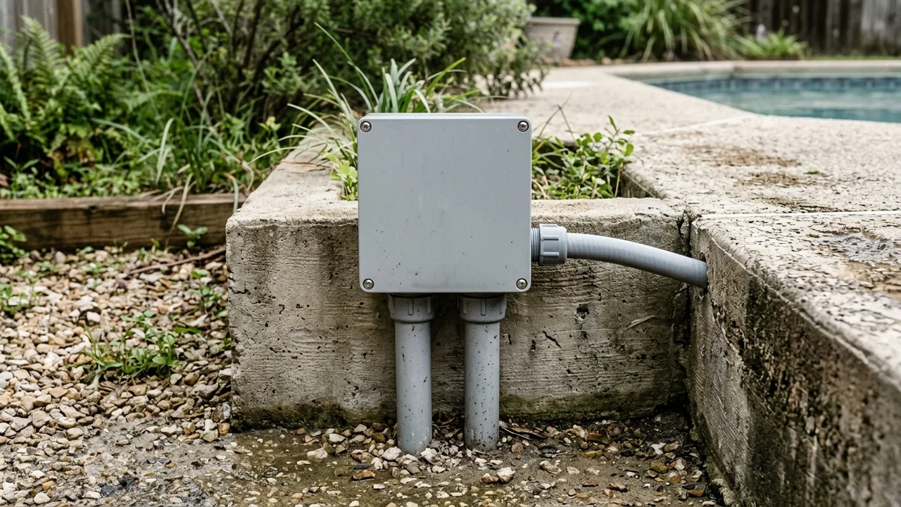
Compare how the retrieved manuals assign physical locations and wet-zone protections:
| Document & configuration | Where the control board / switch lives | What enters the recessed cover vault | Required vault & wet-zone protections stated in manual |
|---|---|---|---|
Latham / Coverstar 1403.pdf (A2463/A2469 Touchpad, 110VAC 3-wire 3/4 HP motor) |
Touchpad controller in a standard-depth single-gang all-weather box with 100% view of the pool surface | 110VAC directional motor leads (Red, Blue), White neutral, and Green ground |
Motor connections made in an all-weather box mounted as high as possible in the cover box; watertight connections at all wire junction locations; 15A GFCI breaker at panel |
Cover-Pools 800024 & Wiring-Pg7.pdf (Save-T 3 / Autosave with Auto-Shutoff) |
Poolside 5V key switch or CoverLink pad in full view of pool; Auto-Shutoff board in an 8"×8"×4" outdoor enclosure outside the cover housing or at the equipment pad | 120VAC motor power (and sensor leads where applicable) to vault J-box and 36" waterproof flex conduit with 1/2" NPT watertight connector | Conduit on motor end protruding no more than 4" into box and within 6" max of top of box (Save-T 3); 3" housing drain kept free of debris; #8 bonding wire at both ends; 15A dedicated GFCI breaker |
Cover-Pools 800235 REL-0001 (T4 Versa with CoverLink wireless control, pp. 12, 16) |
Battery-powered wireless PIN pad mounted in full view of pool; Auto-Shutoff board and CoverLink Receiver in separate enclosures by the motor connected by low-voltage cable |
High-voltage motor leads from Auto-Shutoff/Motor Control Board to electric motor | Keep housing drain free of debris so water drains freely; keep housing lid in place; turn off mains breaker before any inspection or amp-limiter adjustment |
APC DO0392 (DO 0248 Key Switch with Sensor Motor Adapter KA 0384, pp. 58–60) |
Poolside key switch outside housing connected via 5-conductor 18–22 GA low-voltage conduit; dedicated 120VAC 20A GFCI breaker at main panel | High-voltage PVC conduit (three 12 AWG wires) to high-voltage J-box; low-voltage J-box; Sensor Motor Adapter (SMA) and 120VAC 3/4 HP motor |
Secure SMA at the highest point possible to the front of the housing; outdoor-rated PVC high-voltage and low-voltage junction boxes; waterproof strain-relief grommet and 4-pin neoprene-jacketed harness |
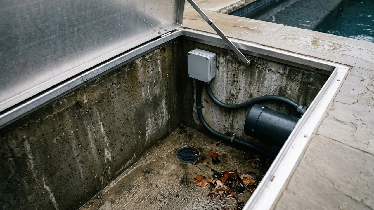
Notice what none of these manuals claim: none of them treats a generic "24V" or "IP68" label as permission to submerge splices or skip GFCI protection, elevated junction boxes, or vault drainage. If a cover vault floods repeatedly or trips its breaker after rain, resolve the water path using the pool cover box and housing guide, pool cover drainage requirements, and automatic pool cover motor problems before re-energizing the circuit.
Copy this 4-column documentation matrix and role checklist before calling the electrician
Use the two tables below to assemble a complete packet before a controller upgrade, motor swap, or rough-in inspection. Only record values you can read from an accessible nameplate or the matched manufacturer manual while the breaker is off or from outside the closed housing. Do not open wet or energized enclosures to guess wire colors. Mark any missing item Unknown / verify on the unit until the cover manufacturer or licensed electrician confirms it.
Part 1: Four-column project documentation matrix
| Column 1: Power Supply & Feeder | Column 2: Motor Assembly | Column 3: Control Signal & Intermediate Board | Column 4: Wet-Vault & Protection Hardware |
|---|---|---|---|
Panel breaker type & amperage: Dedicated GFCI breaker rating (e.g., 15A or 20A for electric; 20A or 30A for hydraulic—verify in manual): __________________ |
Manufacturer & system model: (e.g., Coverstar, Cover-Pools Save-T 3 / T4 Versa, APC, PCS): __________________ |
Poolside control model & part number: (e.g., A2463/A2469, CoverLink, PCS #11722 key switch): __________________ |
Vault junction box elevation: Mounted as high as possible in housing or outside housing wall: __________________ |
Supply voltage & phase: (e.g., 110VAC–120VAC single-phase, or Unknown / verify on the unit): __________________ |
Motor nameplate voltage, HP & amps: (e.g., 110V–120VAC, 3/4 HP or 1/4 HP, full-load amps): __________________ |
Control architecture: Direct 110V–120V switch vs low-voltage signal to Auto-Shutoff / SMA / control board: __________________ |
Watertight conduit & fittings: (e.g., 36" waterproof flex conduit with 1/2" NPT watertight connector, strain-relief grommets): __________________ |
Feeder conduit & wire gauge/count: Run length (under or over 50 ft) and conductor count from panel to board/switch: __________________ |
Motor lead configuration: (e.g., 3-wire Red/Blue/White + Ground vs 4-pin factory plug harness): __________________ |
Signal conduit & harness spec: Separate low-voltage conduit required? Conductor count & AWG per manual: __________________ |
Vault drain & bonding: 3" floor/wall drain clear of debris; #8 pool bonding lugs connected at required ends: __________________ |
Manual title & revision date: Exact PDF/document number and revision used for feeder specs: __________________ |
Manual title & revision date: Exact motor/mechanism diagram matched to serial number: __________________ |
Sightline & mounting height: Standard single-gang weather box in 100% full view of pool surface: __________________ |
Isolation before service: Mains GFCI breaker location verified for lock-out/shutoff before opening any cover or box: __________________ |
Part 2: Three-role confirmation checklist
| Project role | What this person provides or confirms before work starts | What this person must NOT assume |
|---|---|---|
| Owner or builder | Provides existing system brand, serial/model records, photos of accessible exterior labels, desired poolside switch location with 100% pool visibility, and confirms the cover vault drain is clear. | Must not assume a "low-voltage key switch" listing eliminates the need for a dedicated GFCI circuit, a second conduit, or an intermediate control board. |
| Cover installer or dealer | Confirms exact compatibility between the existing motor, torque/amp-limiter or SMA board, and the replacement key switch or keypad; supplies the matching revision of the manufacturer's wiring diagram; calibrates travel limits and clutch/amp-limiter settings after power is live. | Must not splice into unverified household circuits or leave low-voltage or high-voltage splices resting on a damp vault floor. |
| Licensed electrician | Verifies dedicated GFCI breaker sizing, conductor gauge for the actual conduit run length, separation of high-voltage and low-voltage conduits where required, weatherproof/watertight junction terminations, and pool equipotential bonding per local code. | Must not guess directional motor leads or control-board pinouts from wire insulation color alone when the manufacturer's schematic is missing. |
Common questions before replacing a pool cover switch or wiring a vault
Can I replace a standard key switch with a digital touchpad using the same wires in the wall?
Only if the target touchpad manual specifies the exact same conductor count, wire gauge, and voltage path already installed in your conduit. For example, Cover-Pools shows a standard 120V key switch using high-voltage conductors (800024, page 5), whereas adding an Auto-Shutoff with wired CoverLink control (800024, page 6) requires separate low-voltage signal wiring to an Auto-Shutoff enclosure plus main power to that board. Compare both manuals before ordering parts.
If my poolside switch is low-voltage, why did the GFCI breaker trip after heavy rain?
Because the poolside switch is only the trigger; 110VAC or 120VAC line power still feeds the motor control board and the electric motor inside or next to the recessed housing. When a blocked vault drain allows rainwater or groundwater to reach the motor housing or a low junction box, the ground-fault circuit interrupter trips to cut line power. Leave the breaker off, clear the vault drain, and have a qualified technician inspect the dry enclosure.
What if the motor label inside the cover vault is worn off or unreadable?
Record the motor specifications as Unknown / verify on the unit in the handover matrix and do not connect a new controller by trial and error. Give the cover dealer photographs of the mechanism frame, the existing switch faceplate, and the exterior control box so they can identify the generation and supply the matching factory wiring diagram before the electrician opens the circuit.
Sources and method
Updated October 2026. This guide is compiled from publicly available manufacturer installation and owner manuals to help owners, builders, cover technicians, and electricians coordinate documentation. It is not a field test, a product ranking, or a substitute for the installation manual and local electrical code governing your specific pool.
- Latham Pool Products / Coverstar: Wiring Instructions — 110VAC 3 Wire Motor Using the Touchpad Pool Cover Controller A2463/A2469 (
1403.pdf, Rev. 1/15/2013), fetched October 17, 2026. Used for 110VAC 15A GFCI supply, single-gang all-weather switch box in 100% view of the pool, 3-wire 3/4 HP motor directional leads (Red/Blue/White), and mounting the motor junction box as high as possible in the cover box with watertight connections. - Cover-Pools Incorporated: T4 Versa Owner's Manual (
800235 REL-0001), fetched October 17, 2026. Printed pages 3, 12, 14, 16, and 20: breaker shutoff warnings, housing drain maintenance, auto-shutoff amp-limiter function, and the page 16 wiring diagram distinguishing(LOW VOLTAGE WIRES)between the Auto-Shutoff/Motor Control Board and CoverLink Receiver from(HIGH VOLTAGE WIRES). - Cover-Pools Incorporated: General Installation Overview (
800024 PUBL) and CoverLink Electrical Sheet (2015-GENERAL-INSTALLATION-Wiring-Pg7.pdf), fetched October 17, 2026. Printed pages 5–7 and 16–17: contrast betweenKey Switch 120V (high-voltage only)andKey Switch 5v/CoverLinklow-voltage control wiring with an exterior Auto-Shutoff board, 15A dedicated GFCI breaker, 36-inch waterproof flex conduit with 1/2-inch NPT watertight connector, and 3-inch housing drain. - Automatic Pool Covers, Inc. (APC): Specification Book 2025 V2.1 (
DO0392-Spec-Book-2025-V2-1.pdf), fetched October 17, 2026. Printed pages 56 and 58–66 (DO-0325,DO-0321,DO 0248,DO-0330,DO-0034): comparison of direct 120VAC touchpad/switch wiring versus low-voltage key switch and 8-conductor × 22 AWG harness with Sensor Motor Adapter (SMA KA 0384) mounted at the highest point in the recessed housing, 120VAC 20A dedicated GFCI breaker, and power-off connection warnings. - Automatic Pool Cover Parts: Pool Cover Specialist (PCS) Low Voltage Key Switch listing and JustAnswer electrical question on a 1/4 HP 115VAC pool cover motor, fetched October 17, 2026. Used only to illustrate what information is missing when an owner or electrician relies on a spare-part listing or a bare motor rating alone.