Updated November 2026
Pool Cover Key Switch: Operation, Wiring, and Replacement
A pool cover key switch is a spring-loaded or momentary contact control, so the cover stops when the switch is released, and its fixed location is in the line of sight of the complete pool cover. All switches must be mounted in full view of the cover operation. Remove the control key from the key switch, and store it in a secure location to prevent unauthorized operation. On a keyswitch with a slip clutch, turn the key in the cover direction until the pool is completely covered. The auto-shutoff keyswitch contains a safety feature that requires two turns before operating the cover.
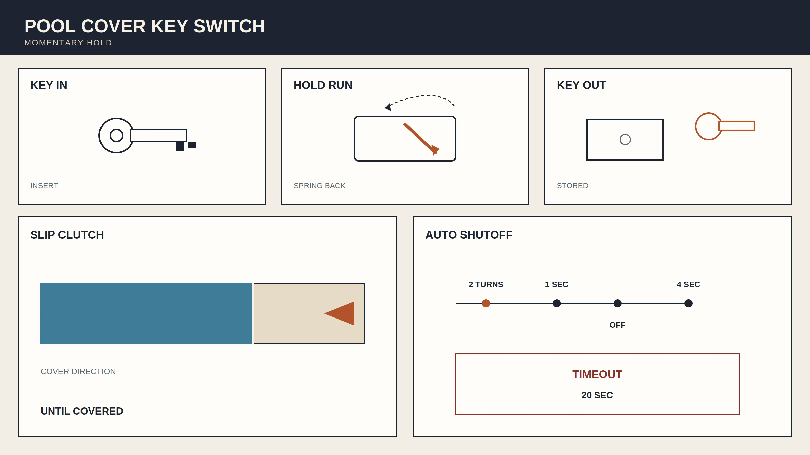
How do a slip-clutch keyswitch and an auto-shutoff keyswitch run?
The operating manual file is numbered 800210 REL-0003. That file prints the slip-clutch hold and the auto-shutoff sequence as separate procedures.
Turn the key to cover or uncover for 1 second, briefly return to off, then operate the cover within 4 seconds. If that auto-shutoff keyswitch is left inoperative for more than 20 seconds, it times out and the key must be turned twice to reactivate it.
For undertrack systems, release the key or control pad a few inches before the end of the pool. Section 10.2 says the cover shall be reversible from a full stop at any point without completing the full open or closed cycle. Annex A1.10.1 says operator-controlled momentary contact switches afford greater control in an emergency.
The lubrication table lists the key switch tumbler with graphite lock lube, twice per year. Never allow children to operate the cover. Be sure you have full view of the spa area when operating the cover. The live how-it-works page already says the key asks the drive to run in one direction until a limit stops it, and that the key is not a throttle. Encoder and travel-limit settings stay on the limit switch guide.
The reprint is designated F1346-91, reapproved 2010. When correctly installed and used in accordance with the manufacturer's instructions, the specification is intended to reduce the risk of drowning by inhibiting the access of children under five years of age to the water. The active catalog page for F1346-23 prints the same scope purpose: safety-cover requirements intended to reduce drowning risk for children under five when the cover is installed and used to the manufacturer's instructions. Section 10 sentences on this page are from the F1346-91 (2010) reprint. Section 10.1 says the open-close switch shall be spring-loaded or of the momentary contact type, so that when released, the cover stops immediately at any point in the cycle. Section 10.3 says electrically operated control switches and motors shall be installed in accordance with the National Electrical Code Article 680-26.
Where must a pool cover key switch be mounted?
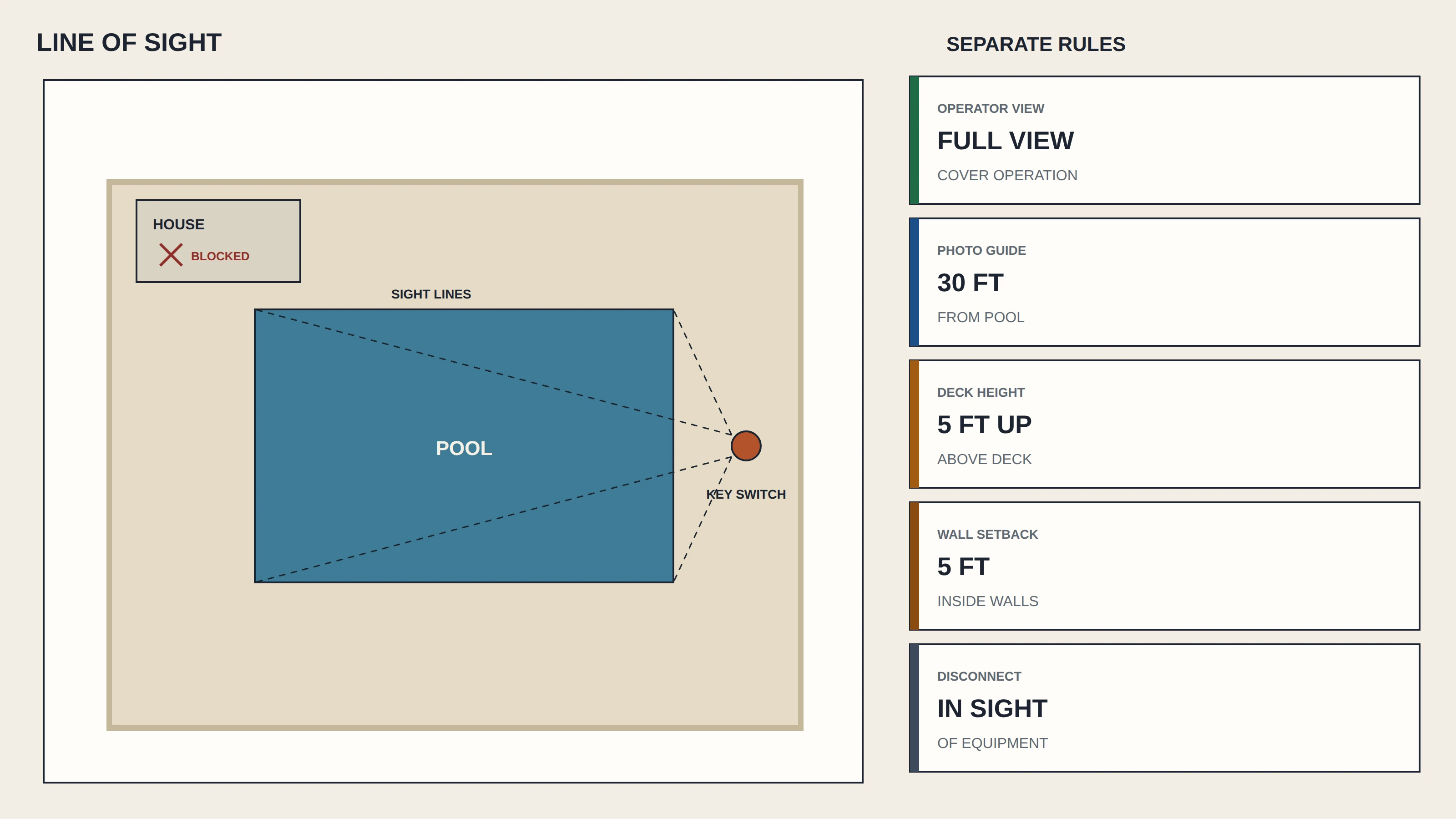
Operator view of the cover and the maintenance disconnect are printed in different documents. Read each distance with the sentence that carries it.
Section 10.4.1 says the control's fixed location is in the line of sight of the complete pool cover, or by its operating process, so the operator is in complete view of the cover during closing. The auto-shutoff drawing says all switches and control pads must be mounted in full view of the cover operation. The control pad must be mounted permanently on a wall in full view of the cover. Do not remove the control pad and carry it like a portable remote.
The Coverstar fiberglass photo guide says the switch must be located where the entire surface of the pool is visible to the operator. That text recommends that the switch be no more than 30 feet from the pool. The switch should never be located inside the home or other building unless it is an indoor pool, and then the switch must be in the same room.
The Latham touchpad sheet says the control switch must be mounted where 100% of the pool surface is visible. Coverstar's safety page says any device used to control the automatic pool cover has to be permanently mounted in full view of the entire pool.
Section 10.4.2 says switching devices shall be key-operated or locked away or able to be deactivated or otherwise located in an inaccessible location, and an inaccessible location shall be at a height of at least five feet above the deck.
The checklist says verify all switches are at least 5ft from the inside walls of the pool or are separated by a permanent barrier, and it cites 680.22(C). The checklist says verify a maintenance disconnect is installed, not an emergency disconnect, and it cites 680.13.
The Dover handout labels its pool rules as 2017 NEC requirements. The Dover handout says 680.13 maintenance disconnecting means shall be readily accessible, within sight of the utilization equipment, at least 5' horizontally from the inside wall, and shall disconnect all ungrounded conductors.
The summary title is 2017 NATIONAL ELECTRICAL CODE & SPS 316. The Mount Pleasant summary says 680.13 requires a means of disconnection, such as a switch or plug, within sight of the equipment served.
How is a pool cover key switch wired?
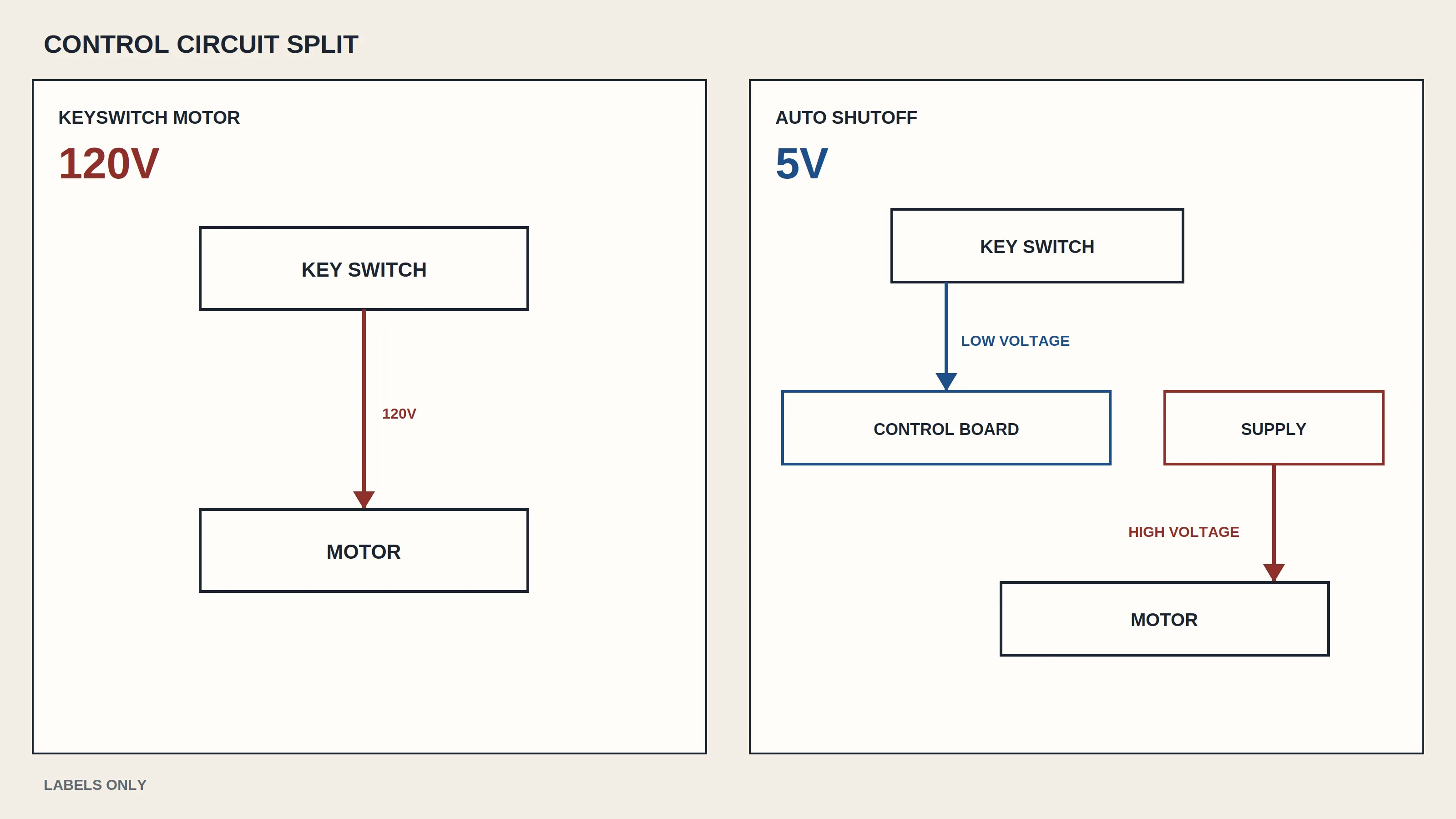
The standard-equipment diagram is headed Electric Motor w/ Keyswitch (Standard Equipment). That standard-equipment diagram labels the control Key Switch 120V. The auto-shutoff option labels the poolside control Key Switch 5v. The same option calls the poolside run wires for a low voltage key switch. The CoverLink diagram prints the label (LOW VOLTAGE WIRES). The same diagram prints the label (HIGH VOLTAGE WIRES).
The installation overview says these are minimum recommendations only. All local and federal codes of standard safe practices must be followed. The live vault-wiring page says low voltage almost always describes the operator signal between a poolside key switch or keypad and an intermediate control board, not the power driving the motor. Feeder sizing and the bond stay on the automatic pool cover electrical requirements page.
The Latham sheet is wiring instructions for a 110VAC 3 wire motor using touchpad pool cover controller A2463/A2469. The sheet is marked REV. 1/15/2013. The control switch is mounted in a standard depth single gang all weather box.
Why is a pool cover key switch not working?
The CoverLink digital control deactivates after 20 seconds without input. A timeout on the auto-shutoff keyswitch is a different pause from a dead control. The slip clutch may need adjustment if the cover pauses as it travels or will not complete the open or close cycle. Water on the cover, low pool water level, bad track pulleys, and dirt or debris in the track can all cause the clutch to slip. If the clutch is slipping for those reasons, fix the problem and do not adjust the slip clutch. Clutch adjustment stays on the slip clutch guide.
Power to the cover comes off at the mains circuit breaker before adjustment or other maintenance. The live parts hub lists the control as a key switch or station, and the cue it names is a dead switch with a live feed.
If the power does not come on the display, the sheet says to check the power supply for 110v. If the display has power but the motor does not run at all, the sheet says to check the neutral wire.
Which replacement key matches the switch?
Match the key in hand to the printed listing. The parts list prints separate keys.
The parts list prints 050555 as a keypad with a single-gang motor control assembly. The note under that keypad says it is for slip clutch systems only and is not compatible with auto-shutoff systems. The footer beside this parts section reads Fluidra 2026 Product Catalog.
| Key style | Parts-list line |
|---|---|
| Elektra gray key | The parts list prints 050401 as Key Switch Replacement Key Elektra (Gray). |
| AB red key | The parts list prints 050329 as Key Switch Replacement Key 22mm AB (Red). |
| Toggle switch key | The parts list prints 050483 as Toggle Switch Replacement Key. |
| Molded black key | The parts list prints 050007 as Key Molded Black for use with Kosa and low voltage switches. |
| Kosa blue key | The parts list prints 050396 as Key Molded Kosa 2 Blue. |
Key switch or touchpad: which control fits?
A Latham article says an automatic pool cover usually contains an electronic data pad, a touchpad, a key operated mechanism, or another easy type of switch to activate the motor. The same article describes activation by an electrical switch or by keying in a code on a touchpad. Coverstar's safety page says the control switch requires a key to unlock the cover plate or a four-digit code to gain access.
The CoverLink wireless control uses a PIN instead of a key. CoverLink control on this manual uses a four-digit PIN and the cover button, held until the pool is covered. The CoverLink control pad must be mounted in full view of the pool cover. Manual 800210 prints a master PIN stored in memory location 1, and it prints the factory default master PIN 1583. Up to 4 unique four-digit PINs can control access to the pool cover. Up to 3 separate control pads can operate the same pool cover.
The photo guide says the standard toggle is not available for the CS300-HD Spa. The same control-switch list names Touch Pad and WIFI Touch Pad as their own lines. The same list names a rocker switch.
What goes on the electrician handoff checklist?
Photograph the switch face, the key, and the drawing label before anyone orders a replacement. Copy the lines below into the note you hand across.
- Before adjustment or other maintenance, turn off the power to the cover at the mains circuit breaker.
- Confirm the control key is out of the switch and stored in a secure location.
- If the auto-shutoff keyswitch is left inoperative for more than 20 seconds, it times out and the key must be turned twice to reactivate it.
- Fix water on the cover, low pool water level, bad track pulleys, and dirt or debris in the track before anyone adjusts the clutch.
- The Latham touchpad sheet says to use a 15amp GFCI breaker at the panel.
- Feeder sizing and the bond stay on the electrical requirements guide.
- Vault junctions and harness gauges stay on the low-voltage vault guide.
Sources
Operating sequences, drawing labels, and placement lines cited above come from these documents. The active catalog page for this safety-cover scope is the catalog edition. The reprint supplies the operating-control sentences.
- Cover-Pools owner's manual for the key sequences, the key storage line, and the lubrication table
- Cover-Pools Versa owner's manual for the CoverLink timeout and the wire labels
- Cover-Pools installation overview for the key-switch drawing labels
- Cover-Pools parts list for the replacement keys and the keypad note
- Latham touchpad sheet for the visibility line, the display checks, and the breaker line
- Latham article for the switch types
- Coverstar photo guide for switch placement
- Coverstar safety page for the full-view control
- Dover handout for the maintenance disconnect
- Mount Pleasant summary for the within-sight disconnect
- Connecticut checklist for the inside-wall switch item and the maintenance-disconnect item
Parent hub: Automatic pool cover parts