Updated October 2026
Automatic Pool Cover Construction Coordination
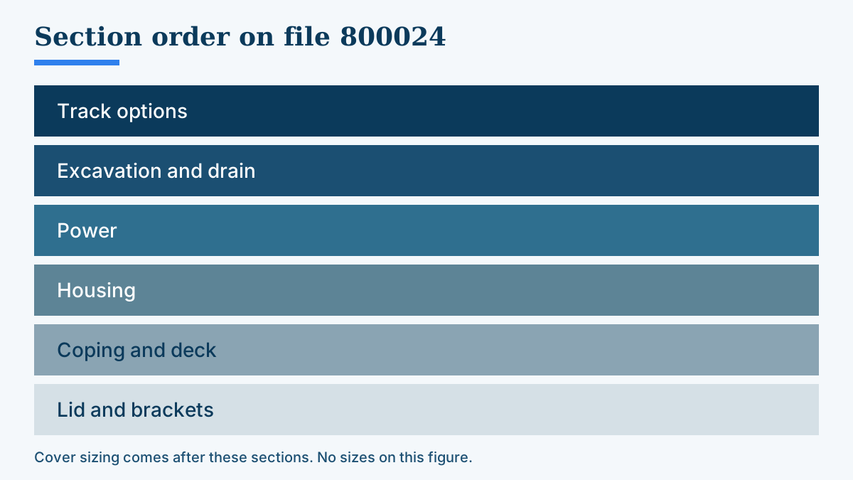
Pouring the coping before the track family is chosen wastes the seat an underside track needs. Coordination on Cover-Pools file 800024 Rel-0024 is the section order: track, excavation and the 3 in drain, power, housing, coping, then the lid. Cover sizing comes after those lines are on the drawing.
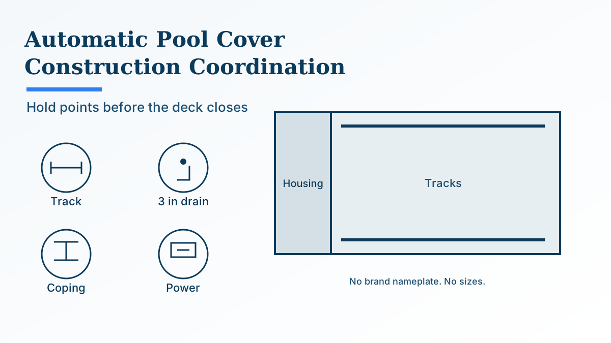
What has to be locked before the deck closes?
Coordination on Cover-Pools file 800024 Rel-0024 is which line has to be true before the next trade pours a Save-T 3 cover system or an Autosave spa cover. Track options are the first section. Excavation and plumbing follow, with the 3 in drain in the recessed housing. Electrical is the choice of an electric motor or a hydraulic power unit. Mechanism housing is next. Coping and deck follow. The lid and its brackets are the recessed-box cover. Cover sizing is later, once those lines are on the drawing.
The parent page is automatic pool cover installation. A shell that is still open is covered on automatic pool covers for new construction. The figure lists the section names in file order. After the track page, the footer number and the section number are different, so the figure does not print a page number.
What is the rule when the coping is thin or the run is long?
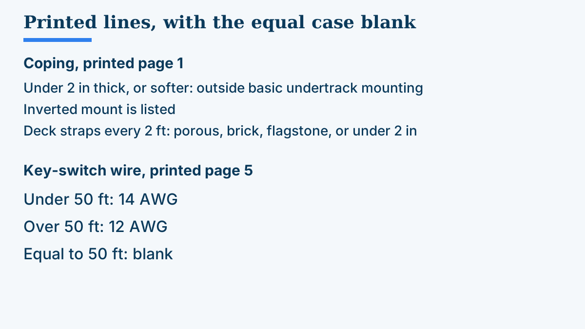
Rule of thumb. If the coping or the deck surface is under 2 in thick, or the material is softer, printed page 1 does not treat that surface as basic undertrack mounting conditions. Inverted mount is the listed path for flagstone, slate, or tile in that case. Deck straps are mounted every 2 ft of track for porous coping, brick, flagstone, and materials under 2 in thick. Lock that choice on pool cover coping integration before the coping is poured.
If the electric key-switch run is under 50 ft, printed page 5 prints 14 AWG. If the run is over 50 ft, that diagram prints 12 AWG. The conduit to the hydraulic pump junction box uses the same under-and-over split. The hydraulic key-switch conduit on that page is 12 AWG minimum. That 12 AWG minimum is separate from the 14 AWG under-50 line, which the electric-motor diagram and the pump conduit both print. Switches on both diagrams must be mounted in full view of the cover operation. The circuit and the bond are on automatic pool cover electrical requirements. Motor height and the hose path are on hydraulic pool cover system design.
Worked example. The 49 ft run and the 51 ft run are arithmetic stand-ins so the under and over sentences can be shown. The file does not print either length. Arithmetic: 50 - 49 = 1, so 49 ft is 1 ft under 50 ft, and the key-switch diagram prints 14 AWG. Arithmetic: 51 - 50 = 1, so 51 ft is 1 ft over 50 ft, and the diagram prints 12 AWG. A run of 50 ft sits in neither sentence. That cell stays blank.
Which printed lines are the hold points?
An empty cell means the file prints no value there. Track space, the diagonals, and the 6 ft, 8 ft, 10 ft corner stay on how to measure a pool for an automatic cover. The housing rows below are the Save-T 3 underside table on printed page 7. On those three rows the motor length is 32 in, the opposite end is 10 in, the beam is 8-12 in, and the throat is 2 in minimum to the finished beam. Depth and width are the cells that change. The opening and the roller stay with pool cover boxes and housings. The 3 in drain continues on pool cover drainage requirements.
| Input or item | Printed value or source | Why it matters |
|---|---|---|
| Track surface, printed page 1 | Under 2 in thick, or a softer material, is outside basic undertrack mounting. Inverted mount is listed for that case | The track choice is locked before the coping is poured |
| Deck straps, printed page 1 | Every 2 ft of track, for porous coping, brick, flagstone, and materials under 2 in thick | Strap spacing is part of that track choice |
| Over-dig, printed page 3 | 18 in beyond the forms at the recessed cover-box end | The dig is past the forms, before the box wall is shot |
| Plumbing keep-out, printed page 3 | Do not install plumbing within 14 in of the deck in the housing area | Pipes in that band sit in the housing zone |
| Housing drain, printed page 3 | 3 in drain in the floor or the wall of the recessed housing. Printed page 16 lists drain to air or drain to a pit | The drain is placed with the excavation |
| Drain centerline, printed page 7 | 4 in maximum from the end wall. The drain can be on either end | A centerline past 4 in is outside the note |
| Conduit in the box, printed page 7 | On the motor end. Not more than 4 in into the box. 6 in maximum from the top of the box | A conduit that sticks in farther fouls the mechanism |
| Electrician, printed page 7 | Consult a certified electrician and the pre-wiring diagrams for conduit and bonding | The file names that person for those two items |
| Builder, cover installer, electrician columns | The file does not print a three-column owner matrix | |
| Key-switch wire, printed page 5 | 14 AWG under 50 ft. 12 AWG over 50 ft. 120 VAC 15 AMP dedicated G.F.C.I. | Equal to 50 ft is blank |
| Equal to 50 ft | The wire sentences say under and over | |
| Switch view, printed page 5 | All switches mounted in full view of the cover operation | The operator has to see the cover move |
| Flex at the motor, printed page 5 | 36 in of waterproof flex conduit, 1/2 in NPT, 14 AWG minimum, wire extended 8 in past the conduit end | The whip length is printed |
| Hydraulic motor, printed page 5 | Mounted above ground level | A motor below grade is outside the note |
| Hydraulic hose path, printed page 5 | 3 in conduit, or 3 in poly or PVC, with sweeping bends and no sharp bends. Two 1/2 in hoses over 80 ft | Equal to 80 ft is blank |
| Equal to 80 ft | The hose note says over 80 ft | |
| Hydraulic key switch, printed page 5 | Conduit with 3 identified wires, 12 AWG minimum, plus one ground | This 12 AWG minimum is separate from the 14 AWG under-50 line on the electric-motor diagram and the pump conduit |
| Panel, printed page 16 | 15-amp GFCI dedicated circuit for the mechanism at the panel. 20 AMP for hydraulic | Printed page 5 names the electric-motor supply as 15 AMP |
| Voltage labels | Printed page 5: key switch 120V and 120 VAC. Printed page 16: 110 V motor and a hard-wired 3-wire key | The file prints both labels and does not equate them |
| Concrete box, printed page 16 | Concrete, gunite, or shotcrete, minimum 6 in thick, 3500 PSI, no rebound | Thickness and strength are cost rows, separate from the mechanism price |
| Save-T 3 box under 55 ft long x 24 ft wide, printed page 7 | Depth 12-1/2 in minimum. Width 12-1/2 in minimum | Motor 32 in, opposite 10 in, beam 8-12 in, and throat 2 in minimum are shared with the other two rows |
| UPB box, printed page 7 | Pools up to 55 ft long. Depth 13 in. Width 13 in | A different row from the standard underside box |
| Save-T 3 box over 55 ft long x 24 ft wide, printed page 7 | Depth 14-1/2 in. Width 14-1/2 in. The sheet prints minimum on the under-55 row, not on this row | The over label on that table |
| Over 65 ft long or 25 ft wide, and vanishing-edge pools, printed page 7 | Call Cover-Pools. No box size is printed | The under-55 minimums are not a substitute |
| Exactly 55 ft, standard box | Under 55 and over 55 leave the equal case out. The UPB row says up to 55 ft and is a different box | |
| Track clearance, printed page 7 | Minimum 2 in clearance for tracks | Side-view note on the underside box |
| Walk-on lid, printed page 13 | Concrete housing, or a wood housing with a concrete wall poured behind the box | The brackets need that anchor |
| Tray size, printed page 13 | Maximum width 24 in. Maximum length 24 in | A tray past either maximum is outside the note |
| Bracket spacing, printed page 13 | Two feet maximum on the 18 in stainless bracket, for trays 18 in to 24 in wide. The 12 in bracket is for a tray under 18 in | Spacing and tray width are paired |
| Extra deck thickness, printed page 13 | The note says the deck must be thicker for an extended tray if the leading edge fits under the tray, and it says to contact Cover-Pools. No thickness is printed | |
| Square-foot line, printed page 16 | Unit price based on track space times pool length, including steps, plus options. No dollar amount | The other rows on this table sit outside that product |
What fails when a hold point is skipped?
Each miss below is a line the file already prints. The prevention is the line that has to be locked before the next pour.
Scroll sideways to compare every column.
| Hold point | Printed miss | Dominant failure mode | Prevention on the sheet |
|---|---|---|---|
| Thin coping poured as an underside seat | Page 1: under 2 in, or softer, is outside basic undertrack mounting | The track has no seat that page accepts | Use inverted mount or deck straps before the pour |
| Plumbing in the housing band | Page 3: no plumbing within 14 in of the deck in the housing area | The pipe occupies the housing zone | Keep that band clear and place the 3 in drain |
| No housing drain | Page 3: place a 3 in drain in the floor or the wall | Water stays in the mechanism housing | Name drain to air or drain to a pit from page 16 |
| Switch out of view | Page 5: switches in full view of the cover operation | The operator cannot see the cover move | Mount the switch where the cover is in view |
| Hydraulic motor below grade | Page 5: hydraulic motors must be mounted above ground level | The motor sits below the printed height | Set the pump unit above grade |
| Sharp bend in the hose pipe | Page 5: sweeping bends, no sharp bends, 3 in conduit | The hose path kinks | Use the sweeping 3 in pipe |
| Walk-on tray without the concrete anchor | Page 13: concrete housing, or a concrete wall behind a wood box | The brackets have nothing to anchor to | Pour that wall before the tray is set. Lid choices are on pool cover lid options |
| Under-55 box used on the call line | Page 7: over 65 ft long or 25 ft wide, and vanishing-edge pools, call. No size is printed | A minimum from another row is used where the table prints none | Leave the size blank and follow the call line |
Which cost rows sit outside the square-foot line?
Printed page 16 puts the mechanism unit price on track space times pool length, including steps, plus options. The same page lists other rows and prints no dollar amount: housing excavation, the 3 in drain, conduit, the dedicated GFCI, the concrete box, tile on the lower beam, track options, the lid or bench, and power options. Those rows are the scope beside the mechanism line. The square-foot arithmetic stays on the measurement page linked above. Lid scope is on the lid page linked in the failure table.
When do these rows not apply?
Printed page 2 places universal track and SnapTop track on a deck that is already finished, on the deck surface. Flush track is for a new pool or a pool already built, set flush with the deck, and the sheet recommends it for indoor use only. Printed page 4 sets a flush track 6 in back from the pool edge, and it says a universal track may be mounted at the pool edge. A finished deck is automatic pool covers for existing pools.
Printed pages 8 and 9 are the Autosave box tables. The depth and width minimums in the hold-point table are the Save-T 3 underside rows on printed page 7, including the UPB row on that page. They are separate from the Autosave minimums.
Printed page 5 labels the electrical figures as minimum recommendations only. It requires local and federal codes, and it sends conduit details to the prewiring instructions. The repeated footer says all diagrams are for general information and says to consult the installation instructions. The cover requires a contractor licensed and qualified in pool equipment where that jurisdiction has such a requirement. Where it does not, the cover requires a professional able to follow the instructions exactly.
A standard-box length of exactly 55 ft, a wire run of exactly 50 ft, a hose note of exactly 80 ft, and the extra deck thickness for an extended tray are blank. No dollar amount is printed on the cost page.
Method and sources
Updated October 2026. Lengths in the worked example are marked as arithmetic. An empty cell means the file prints no value there.
The source PDF is Cover-Pools, General Information for Installing an Automatic Pool Cover, file 800024 Rel-0024. Printed page 1: surfaces under 2 in thick, deck straps every 2 ft. Printed page 2: universal and SnapTop on a finished deck, flush track recommended for indoor use only. Printed page 3: 18 in over-dig, plumbing within 14 in of the deck, 3 in drain. Printed page 4: flush track set back 6 in, universal track at the pool edge. Printed page 5: 14 AWG under 50 ft, 12 AWG over 50 ft, 15 AMP dedicated G.F.C.I., switches in full view, 36 in flex, hydraulic motors above ground, 3 in conduit with no sharp bends, two 1/2 in hoses over 80 ft, hydraulic key switch 12 AWG minimum. Printed page 7: conduit limits, drain centerline 4 in maximum, certified electrician, Save-T 3 box rows, call line for over 65 ft or 25 ft wide and vanishing-edge pools, 2 in track clearance. Printed page 13: walk-on lid anchorage, tray maximum 24 in by 24 in, bracket spacing two feet, deck thickness not printed. Printed page 16: 6 in concrete at 3500 PSI, 15-amp GFCI and 20 AMP hydraulic, 110 V motor label, unit price with no dollar amount.
Questions
- Does file 800024 name a builder, a cover installer, and an electrician as the owner of each row?
- It names a licensed contractor for installation and service, where the jurisdiction requires that license, and it says to consult a certified electrician for conduit and bonding. It does not print a three-column owner matrix. Owner cells the file leaves off stay blank.
- Does printed page 13 state the extra deck thickness for an extended tray?
- No. It says the deck thickness must be increased for extended trays if the leading edge is going to fit under the tray, and it says to contact Cover-Pools. No thickness is printed.
Parent hub: Installation