Updated October 2026
Automatic Pool Cover for New Construction
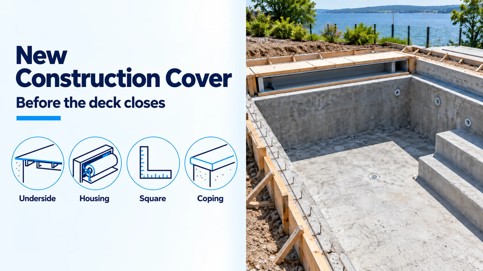
Pouring coping over a bond beam that sits level with the side walls wastes the cantilever and leaves the underside track with no slot. An automatic pool cover for new construction is locked in while the shell, the coping, and the housing excavation are still open.
An automatic pool cover on a new pool is set with the shell. Cover-Pools states that most new rectangular concrete or gunite pools use underside track under the overhanging coping or in a track channel, with the mechanism typically below the deck, and that this track is provided before construction. Coverstar states that tracks must form a rectangle for the cover to open and close, and that under-track systems under the coping or in the wall are its new-pool path, with the drive recessed. A Coverstar poured flush guide is a different sequence: the housing is at least 12 inches from one end, the guides extend 18 inches past the other end, and the guide is in place before the pour. Each number below stays on the sheet that prints it.
| Input or item | Typical value or source | Why it matters |
|---|---|---|
| Underside track, Cover-Pools track systems page | Most new rectangular concrete or gunite pools; provisions before construction | The guide is hidden, and the mechanism is typically below the deck |
| Rectangle, 800024 underside excavation | Tracks at 90 degrees to the mechanism and recessed housing; corners square, no radius | A radius at the tile line or the coping binds travel |
| Over-dig, same sheet | 18 inches beyond the forms at the recessed cover-box end | The box sits outside the formed waterline |
| Plumbing clearance, same sheet | No plumbing within 14 inches of the deck in the housing area | A pipe in that band lands in the mechanism |
| Drain, same sheet | 3 inch drain in the floor or wall of the recessed housing | A closed box holds water on the drive |
| Bond beam, gunite layout on 800024 | Shot 2 1/2 inches lower than the side walls; 2 inches lower once finished with tile | That drop is the track opening |
| Cantilever, underside coping sheet | Minimum 2 inches from tile on the side walls; 3 inches from tile on the end opposite the mechanism | The track mounts on the flat bottom of that overhang |
| Coping past the track, same note | No more than 1/2 inch past the track edge | The coping measurement is not the track space |
| Save-T 3 underside box, pools under 55 ft long by 24 ft wide | Motor end 32 in, opposite end 10 in, beam 8 to 12 in, throat 2 in minimum to the finished beam, depth and width 12 1/2 in minimum | Longer or wider pools use other rows on the same sheet |
| Poured flush guide, Coverstar 0903 | Housing at least 12 inches from the pool end; guides extend 18 inches past the other end; supports no farther than 5 feet | The guide is cast in before the deck pour |
The whole sequence belongs on the automatic pool cover installation page. The hidden guide itself is the undertrack automatic pool cover.
Write the track on the coping detail
Cover-Pools names underside track for most new rectangular concrete or gunite pools. The track sits under the overhanging coping, or inside a track channel, and the mechanism is typically below the deck. The same page says provisions for this track have to be made before construction. Track channel is the version that goes into the wall. Cover-Pools states that the channel lets underside track serve a raised wall, thin coping, a vinyl liner, or a fiberglass shell, and that the channel removes the cantilever because it sits flush with the pool wall.
Coverstar sorts the new-pool guides on its options page. Under track is embedded in the wall or mounted on the underside of a rectangular pool's coping. The page calls that path the one for new pools or a deck resurfacing, with the drive recessed. Encapsulated under track is also the page's pool-in-pool note for a freeform shape. The cover path is still a rectangle: the same page says tracks must be installed in a rectangular shape around the pool for the cover to open and close. A freeform waterline that cannot hold that rectangle is a freeform pool problem, not a coping texture.
Recessed top track is the deck-level new-pool option on that Coverstar page. For new pools or a resurfacing, it offers a recessed vertical track, or a recessed horizontal track that can be sloped for a flush aluminum or stone lid. That cut is the recessed top track layout. The screw-down horizontal top track in the same paragraph is the existing-pool channel, and it waits until the deck is already finished.
A poured flush guide is a third new-build path, and it is not underside track. Coverstar document 0903 puts the guide at finished deck grade, starting flush with the inside of a housing that is at least 12 inches from the end of the pool, and running 18 inches past the other end. The three guide locations are compared on undertrack versus top track.
| New-build layout | Dominant failure mode and prevention |
|---|---|
| Underside track under coping | A radius corner, or a bond beam shot level with the side walls. Square the finished tile line and shoot the box-end wall 2 1/2 inches lower before coping is set. |
| Track channel in the wall | A cantilever left on a wall that was detailed for a flush channel. Set the channel in the wall. Cover-Pools states that this channel removes the cantilever. |
| Coverstar poured flush guide | Supports farther than 5 feet apart, or cement left higher than the bottom of the channel. Stake the guide, and chip that cement, before the deck is poured. |
| Recessed housing | No 3 inch drain, or plumbing within 14 inches of the deck in the housing area. Place the drain and keep that band clear before the deck closes. |
| Walk-on vanishing lid | A wood box with no concrete wall behind it. The overview requires a concrete housing, or a concrete wall poured behind a wood box, before the brackets are anchored. |
Takeaway: the coping detail has to name underside, track channel, recessed top track, or a poured flush guide. A rendering with no slot is not a track family.
Shoot the end wall lower than the sides
On the 800024 gunite layout for underside track, the pool wall at the recessed box, the bond beam, must be shot 2 1/2 inches lower than the side walls. The parenthetical on that drawing is 2 inches once the wall is finished with tile. Any interior wall, including a spa wall, is gunited to the same drop: 2 1/2 inches lower, 2 inches lower after tile. The top inside corners above the waterline are square. The drawing forbids a radius there.
The coping sheet that follows uses that drop as the track opening. The opening is 2 1/2 inches at the box and 2 inches finished with tile, then it slopes to 3 inches inside the pool. Side walls need a cantilever of at least 2 inches from the tile. The end wall opposite the mechanism needs at least 3 inches from the tile. Corners of the coping are square. The track mounts on the flat bottom of the coping. The note on that sheet says the coping measurement is not the track space, and that coping must not extend more than 1/2 inch past the edge of the track. The same drawing labels a box minimum of 12 1/2 inches wide by 12 1/2 inches deep beside the 2 inch side cantilever.
The lowered wall is finished with tile. For the lowered edge, the sheet says to use a rounded tile on the front and back edges to limit scraping on the cover.
Rule of thumb: If the bond beam drop is below 2.5 inches at the cover-box end, hold the coping. The sheet's finished figure is 2 inches after tile, and the track opening at the box is that same pair of dimensions before it slopes to 3 inches inside the pool. A wall shot level with the sides has no slot for this track. Gunite elevations for this drop are part of the gunite pool page, and the stone joint is coping integration.
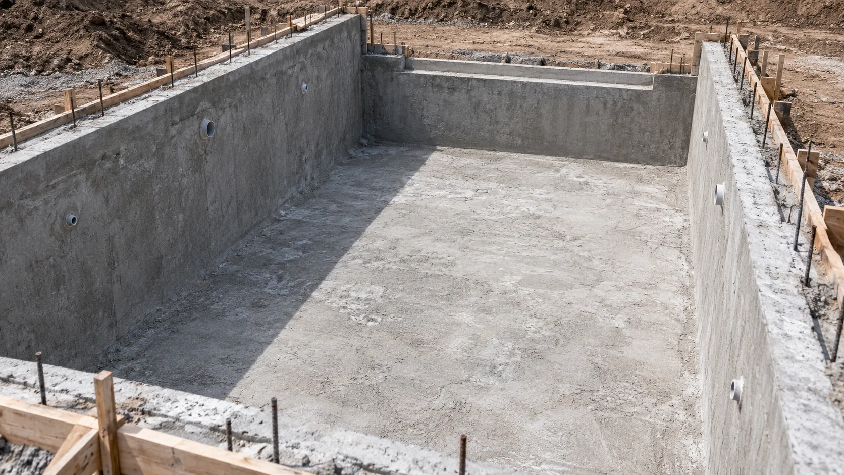
Common mistake: matching the end-wall elevation to the side walls because the coping profile has not been chosen, then discovering the underside opening after the gunite has set.
Dig the box before the deck closes
The underside excavation list on 800024 is six lines. The tracks, and a rectangular pool, must be a true rectangle, perpendicular to the mechanism and the recessed housing at 90 degrees. Over-dig the recessed cover-box end 18 inches beyond the forms, and do not install plumbing within 14 inches of the deck in the housing area. The motor can sit at either end of the box. Do not locate skimmers in the lowered pool wall. All corners are square, with no radius, on the finished tile line or the coping. Place a 3 inch drain in the floor or wall of the recessed housing.
The drawing also labels excavation from the waterline as 36 inches on the motor side and 16 inches on the opposite side, plus the 18 inch over-dig at the box end. Those labels are on a diagram the sheet marks as general information. The installation instructions for the unit still govern the pool in front of you. Use the 18 inch over-dig, the 14 inch plumbing band, and the 3 inch drain as the written holds.
The underside Save-T 3 box table is separate from the Autosave table. For pools under 55 feet long by 24 feet wide, the Save-T 3 cells are a 32 inch motor end, a 10 inch opposite end, a beam of 8 to 12 inches, a throat of 2 inches minimum to the finished beam, and a minimum depth and width of 12 1/2 inches. Pools over 55 feet long by 24 feet wide have their own cells. The row for pools over 65 feet long or 25 feet wide, and for vanishing-edge pools, does not print box cells. It sends that case to Cover-Pools. The Autosave underside tables are limited to pools up to 13 feet or 200 square feet. A Save-T 3 row does not size an Autosave box.
A walk-on Vanishing Lid on the same overview needs a concrete housing. If the housing is wood, a concrete wall is poured behind the box to anchor the brackets. The maximum width of any tray is 24 inches, and the maximum length of a tray is 24 inches. Deck thickness increases for an extended tray when the leading edge fits under that tray. That lid is chosen with the cover box and housing and the lid options. The 3 inch outlet is a cover drainage detail. Conduit and bonding follow the pre-wiring diagrams and a certified electrician, which is the electrical requirements page. This page does not assign a motor rating.
Check the corner with the printed triangle
The underside excavation drawing squares the track to the box with a 6-8-10 triangle. GE is 6 feet, GF is 8 feet, and FE is 10 feet. The same drawing sets AB equal to CD and AD equal to CB.
FE = sqrt(GE^2 + GF^2)
Worked example. GE is 6 ft and GF is 8 ft.
FE = sqrt(36 + 64) = sqrt(100) = 10 ft
A field tape of 6 ft, 8 ft, and 10 ft 3 in misses the printed hypotenuse by 3 inches. Hold the coping and the tile line until FE matches 10 ft. These three lengths are the squaring check on the drawing. They are not the pool length or the pool width.
The overview also prints a track-space limit beside that geometry: track widths over 25 feet, or lengths over 65 feet, require factory approval, and the maximum track space on the sheet is 36 feet. That limit is not a price.
Pour the flush guide only if that is the track
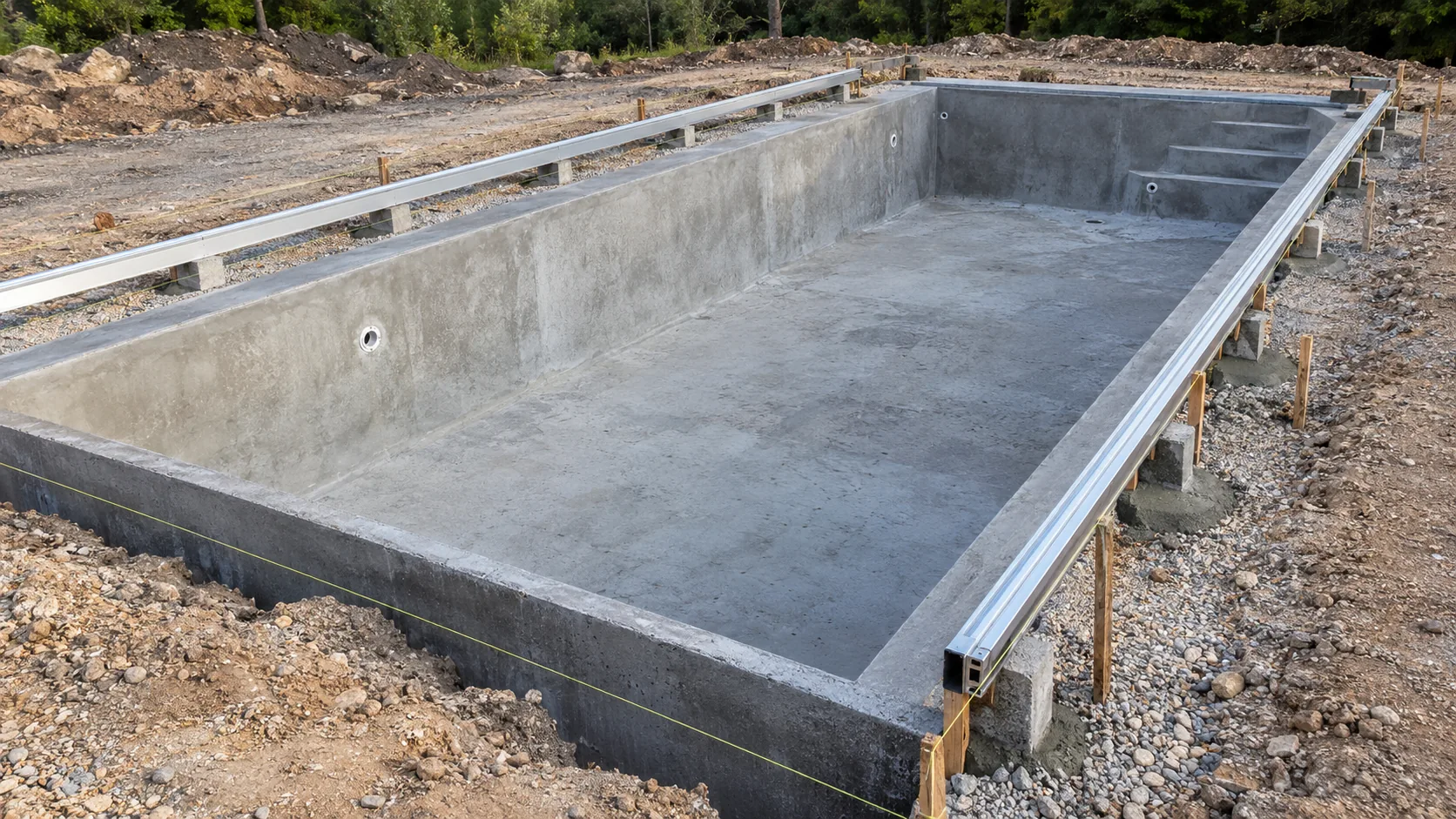
Document 0903, Flush Deck Guide Installation, is the pour-in path. The guides start flush with the inside of the cover housing. That housing is a minimum of 12 inches from the end of the pool, and the guides extend 18 inches beyond the other end. Lengths, the distance between the guides, and the diagonals each have to be equal.
The guides sit exactly at finished deck grade. The sheet recommends keeping the deck level from the pool to the guide housings and starting the slope outside the guides. If a standard lid is used, the deck around the housing boxes stays flat for a minimum of 4 inches before any slope. The guide, a spacer, and top protection are in place before the pour. Supports are no farther than 5 feet apart. One of the three stake methods sets the housing into piles of concrete or gunite about every 4 feet, and cement left higher than the bottom of the channel has to be chipped down before the deck is poured. A string line stays until after the pour.
The standard guide is straight. Optional curved pieces are for a flush deck lid: the deck is lowered 2 inches between the guides, and the box is installed 2 inches lower. The sheet recommends a minimum of 5 to 6 inches of concrete on each side of the housing, with rebar or wire under the housing so the concrete does not crack away from it. Concrete has to come as close to the top of the housing as possible, or the cover does not run as the section requires.
A missed hold comes back as a second visit
This page does not price the work. The overview's cost lines already separate housing excavation, a 3 inch drain to air, and track channel from the track itself. Missing one of those lines is a return to finished concrete.
A bond beam shot level with the side walls means the mason opens a wall that was meant to stay. A radius at the tile line means the coping comes back off. Plumbing inside the 14 inch band means a pipe is in the mechanism space. A missing 3 inch drain means a core through the box. Cement left above a flush channel means the chip-out 0903 already names, before the deck can be poured. A wood housing under a walk-on lid, with no concrete wall behind the box, means the brackets have nothing to anchor to.
Write the track family, the box row, the drain, and the coping cantilever on the project specification checklist. Who shoots the wall, who places the drain, and who owns the conduit belongs on the construction coordination page. Pool builders carry that split across the shell and the cover contract.
When this sequence does not apply
The deck and the coping are already finished. Underside track and a poured flush guide are no longer a formwork choice. Use the existing pool checks, including the screw-down channel Coverstar names for a finished deck. A vanishing-edge pool, and a pool over 65 feet long or 25 feet wide, has no printed box on that 800024 row. A track wider than 25 feet or longer than 65 feet stays inside the factory-approval note, up to the 36 foot track space the sheet prints.
Sources and method
Updated October 2026. This page reads public manufacturer documents for the holds a new shell has to provide before an automatic cover can be built in. The numbers stay inside the system and the pool size each sheet names. Diagrams on 800024 are general information, and the installation instructions for the unit still govern the pool.
- Cover-Pools, track systems page, fetched 17 October 2026 from https://www.coverpools.com/pool-professional/components-and-technology/track-systems-original/. Underside track for most new rectangular concrete or gunite pools, provisions required before construction, mechanism typically below the deck. Track channel for raised walls, thin coping, vinyl liner, and fiberglass, installed flush so the cantilever is not required.
- Cover-Pools, General Installation Overview 800024, fetched 17 October 2026 from https://www.coverpools.com/wp-content/uploads/2016/11/800024-PUBL-GENERAL-INSTALLATION-OVERVIEW.pdf. Underside excavation: 90 degree rectangle, 18 inch over-dig, no plumbing within 14 inches of the deck in the housing area, motor at either end, no skimmers in the lowered wall, square corners, 3 inch drain. Gunite bond beam 2 1/2 inches lower, 2 inches finished with tile. Coping cantilever 2 inches on the sides and 3 inches on the far end, track opening 2 1/2 inches at the box sloping to 3 inches, coping no more than 1/2 inch past the track. Save-T 3 underside box for pools under 55 feet by 24 feet. Autosave tables limited to 13 feet or 200 square feet. Walk-on Vanishing Lid concrete housing and 24 inch tray limit. Track space over 25 feet wide or 65 feet long needs factory approval, maximum 36 feet. Diagrams are marked as general information.
- Coverstar, options and features, fetched 17 October 2026 from https://www.coverstar.com/cover-models/options-features/. Tracks must form a rectangle. Under track for new pools or deck resurfacing, including encapsulated under track in a pool-in-pool application for a freeform shape. Recessed vertical or sloped recessed horizontal track for new pools or a resurfacing. Screw-down horizontal top track for existing pools.
- Coverstar, document 0903, Flush Deck Guide Installation, fetched 17 October 2026 from https://ellispoolcovers.com/wp-content/uploads/2020/05/0903.pdf. Housing at least 12 inches from the pool end, guides 18 inches past the other end, equal lengths, spacing, and diagonals, guides at finished grade, 4 inch flat deck around the housing before a slope when a standard lid is used, supports no farther than 5 feet, cement above the channel chipped before the pour, 5 to 6 inches of concrete on each side of the housing.
The local industry library returned no pool-cover mechanism document for this topic. Cached search data had no stored result for this query, so no competitor page was purchased or used as a fact source.